This thread has been locked.

If you have a related question, please click the "Ask a related question" button in the top right corner. The newly created question will be automatically linked to this question.

TLV320AIC3104 Line input

Other Parts Discussed in Thread: TLV320AIC3104

Hello,

I'm having problems with the single ended line inputs on a AIC3104. I had been driving
them DC coupled, but getting odd results. AC coupling seems to give just as confusing results.

When DC coupled, I had thought it would be 0 to 2Vp. But reading another forum entry seems to tell me
this is not true. Something about a bias voltage of 1.35V and needing the inputs to work from 0.35V to 2.35V.

Next I tried AC coupling. I thought the inputs would swing around 1.35V, but in fact they swing around 0.45V.

Can you please tell me what the real numbers are or what I should be seeing?

  • Hi, Paul,

    Welcome to E2E and thank you for your interest in our products!

    Effectively, the common-mode input voltage is 1.35V when these inputs are AC-coupled. Additionally, the analog inputs would need to be connected to the PGA and the ADC would need to be enabled. Once all these configurations are made, you will see a 1.35V at the inputs.

    If the analog inputs are not AC-coupled, the common-mode voltage won't be generated.

    Best regards,
    Luis Fernando Rodríguez S.
  • Hi Luis,

    Thanks for the reply.

    So for a DC coupled signal, the CODEC wants to see 0 to 2Vdc for a full scale sweep?
    For an AC coupled signal, 0.35 to 2.35V?

    Is this correct?

    Paul
  • Hi, Paul,

    The TLV320AIC3104 analog input accept ranges from 0V to AVDD (please notice that the absolute maximum range is -0.3V to AVDD + 0.3V). So, for a DC coupled signal the codec may accept voltages from 0V to AVDD. For a AC coupled signal, the codec may accept a range from -1.35V (common-mode voltage) to AVDD - 1.35V.

    Best regards,
    Luis Fernando Rodríguez S.
  • Hi Luis,

    I think I know what's going on. When the CODEC is configured for single ended input, should the unused input be grounded or left floating?
    Nothing is stated on way or another in the datasheet.

    Thanks for your help.
    Paul
  • Hi, Paul,

    Effectively, the unused analog inputs should be routed to a 0.47uF capacitor (min) to analog ground. Floated pins can also work, but since the analog inputs are DC biased, it is suggested to route them to this capacitor.

    Best regards,
    Luis Fernando Rodríguez S.
  • Hi Luis,

    Well that was the problem. Both Line1LM and Line2LM were tied to directly to ground. Changing this to 0.47uF caps to ground fixed the problem.

    Thanks again,

    Paul

  • Hi Luis,

    I want to use a line-in connector with LINE1LP and LINE1RP. So I have to add a 0.47µF (or higher) capacitor between, right? And the rest of the unused inputs, I have to add a 0.47µF capacitor to analog ground.

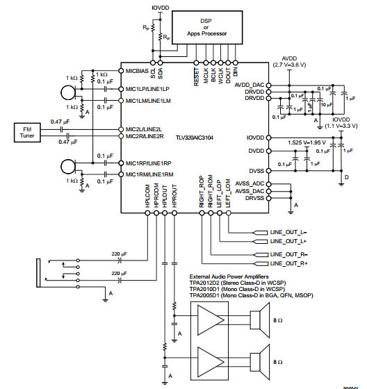
    Why is the microphone (picture below) connected to Pin LINE1LP and LINE1LM? Don´t it have been connected to LINE1LP and LINE1RP?

    Sadullah

  • Hi, Sadullah,

    Correct, for line inputs, the capacitor should be changed. Unused inputs should be AC-coupled to ground through a cap due to the DC offset present on the input pins.

    Mics are connected in differential configuration, so the connection showcased in the diagram is correct as LINE1Lx is configured in differential mode.

    Best Regards,

      -Diego Meléndez López
       Audio Applications Engineer

  • Hi Diego,

    thank you for your answer. Can I use two 1µF capacitors for the line input and 1µF capacitors for the unused pins?

    Sadullah
  • Hi, Sadullah,

    It would depend on your application, the values from the datasheet are implying a recommended cutoff frequency for audio applications (below 20Hz). two 1µF caps in parallel would be good, even using a 1µF cap might work fine. Please refer to table 8.6 of the datasheet to find the input resistance and calculate the input cutoff frequency from there. 

    For the unused pins, 1µF cap should be fine.  

    Best Regards,

      -Diego Meléndez López
       Audio Applications Engineer