Hi,
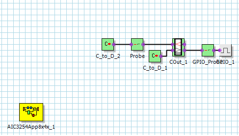
I'm trying to make a Signal to the GPIO Pin. I used the Basic DSP GPIO Output Box, but when compiling Purepath means
Error: Cannot find the template file: Gpio_Output.asmx
What do I wrong?
Micky
Hi,
I'm trying to make a Signal to the GPIO Pin. I used the Basic DSP GPIO Output Box, but when compiling Purepath means
Error: Cannot find the template file: Gpio_Output.asmx
What do I wrong?
Micky