Hi,
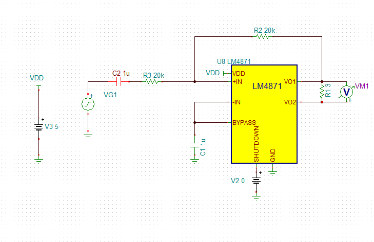
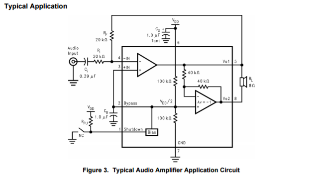
There appears to be a discrepancy from the tina reference design here vs the application circuit in the datasheet for the LM4871. The feedback in tina is run back to the non inverting input.
Simulating with tina makes it appear that the non inverting input may actually just be mislabeled in the macro and is indeed the inverting input (the open loop phase plots seem to match datasheet and appears to be stable over frequency).
The correct circuit topology is the one laid out in the datasheet correct?
Thanks,
Jake