This thread has been locked.

If you have a related question, please click the "Ask a related question" button in the top right corner. The newly created question will be automatically linked to this question.

PCM3070: PCM3070 PLL setting

Part Number: PCM3070


Hello

Would you please advise about PLL setting for PCM3070?

We have problem of THD= over 3% at customer's ES board when fs=44.1KHz it these

a couple of  weeks.   ( When fs= 192KHz, THD < 0.03% and seems OK )

Customer use PCM3070 as following way.

~~~~~~~~~~~~~~~~~~~~~~~~~~~~~~~~~~~~~~~~~~~~~~~~

case1  input i2s data is fs=192KHz. I2S slave. MCLK is 24.576MHz  from Wireless SoC,

case2  input i2s data is fs=44.1KHz. I2S slave.  MCLK is 22.5792MHz from Wireless SoC

~~~~~~~~~~~~~~~~~~~~~~~~~~~~~~~~~~~~~~~~~~~~~~~~~

Therefore, customer and I think following setting is avilable for both case 1 and case2 because MCLK is set differently from SoC.

===

PLL_CLK_IN= 24.576 MHz Or 22.5792 MHz

P=2  ===> PLL_CLKIN/P <  10MHz~20MHz

J.D= 8.0

R=1

So, PLL_CLK= 98.3MHz=CODEC_CLK_IN

NADC=4 ==> DAC_miniDSP is 24.6MHz( <55.2MHz)

MADC=4 ==> DAC_MOD_CLK is 6.14MHz ( <6.2MHz )

AOSR =32

Therefore

DAC_fs = 192KHz Or 176.4 KHz

DVDD =1.8V ( > 1.65V  )

===

I attach the .cfg file.


Question 1

What is  PLL clock range High Or Low? ( Page 0 Reg 4 )

Does it mean Table 2-23  (DVDD >1.26V Or DVDD > 1.65V ) ?


Question 2

If I set DAC_FS as 176.4KHz , I2S data is available not only fs= 176.4KHz data but also

fs=44.1KHz data with no problem?

Also If I set DAC_FS as 192KHz, I2S data is available not only fs= 192KHz data but also

fs=48KHz data with no problem?


Question 3

I understand " DAC_FS"  is sampling rate of DAC for incoming I2S data.

Application Reference Guide **  page 46 says.

2.8MHz < DOSR * DAC_FS < 6.2MHz  

I just follow DOSR * DAC_FS for this criteria, no need to follow DOSR *input fs.

Is is correct?

Question 4

If I violate CODEC_CLKIN  137MHz ( Application Reference guide Table 2-23 )

when I set P=1 , what phenomenon may occur ?


Question 5

I appreciate if you have any advise the check point  for  improving THD.

I recommend  customer that just send i2c address and register value by base_main_Rate_192.cfg file

from MCU.  

But is there any lack  for software implementation ?

I am sorry that I do not know how to use following  well .....

base_main_Rate44_pps_driver.h

pps_driver.c

pps_driver.c

Thank you and with my Best Regards

**

http://www.tij.co.jp/jp/lit/ug/slau332/slau332.pdf

base_main_Rate192_0dB._revised.cfg

  • Hi, Shibatani-san,

    We will check your question, due Holiday, the response may be delayed so we apologize for any inconvenience. 

    Best Regards,

      -Diego Meléndez López
       Audio Applications Engineer

  • Dear Diego-san

    Thank you for your reply.

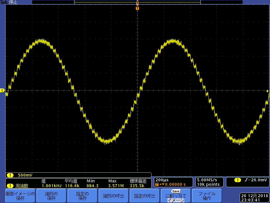
    I attach the waveform when THD is 3% in case fs=44.1KHz , setting is following

    ~~~~~~~~

    MCLK_IN=22.5792MHz

    P=2 R=1 J=8 D=0 

    NDAC=4, MDAC=4

    OSR=32

    DAC_fs is set to 176.4kHz

    2x Interpolation, 1x Decimation.

    Input fs=44.1KHz

    ~~~~~~~~~~~


    Anyway, when I just changed  DOSR =128  in  setting avobe and DAC_fs  =44.1KHz   in  case  input fs= 44.1kHz , THD was significantly improved ; < 0.02%, waveform  improved.

    So, " DAC_fs "must be equal to I2S input fs ....Customer should change the DOSR according  to input fs change .....  is it correct?


    Best Regards


  • Hi, Shibatani-san,

    Normally, the THD issues are related with the PLL and clock dividers configuration.

    As you mentioned, this is related with the AOSR/DOSR values. This device has three possible interpolation and decimation filters (A, B and C). The use of each decimation filter depends of the sampling rate. In cases where 44.1KHz is used, we recommend to select a processing block with a decimation filter A. This filter is used for sampling rates up to 48KHz. As mentioned in the application reference guide ( www.ti.com/.../slaa408a.pdf ), this filter requires an AOSR = 64 or 128.

    In case of higher sampling rates such 192KHz, we recommend to select the decimation filter C. As you may see ( www.ti.com/.../slaa408a.pdf ), it would require a different AOSR (32).

    Regarding your question about the PLL clock range, it is used to modify the admissible clock range. You may take a look at table 2-26 for more details ( www.ti.com/.../slaa408a.pdf ).

    Finally, you are correct. The DAC_fs must be equal to I2S (WCLK) input fs. This will avoid distortion problems in your sampled signal.

    Best regards,
    Luis Fernando Rodríguez S.
  • Dear  Luis san

    Thank you for your advise.

    I will discuss with customer .