This thread has been locked.

If you have a related question, please click the "Ask a related question" button in the top right corner. The newly created question will be automatically linked to this question.

TLV320ADC3101: AMIC configuration / Setting for ADC - TLV320ADC3101

Part Number: TLV320ADC3101

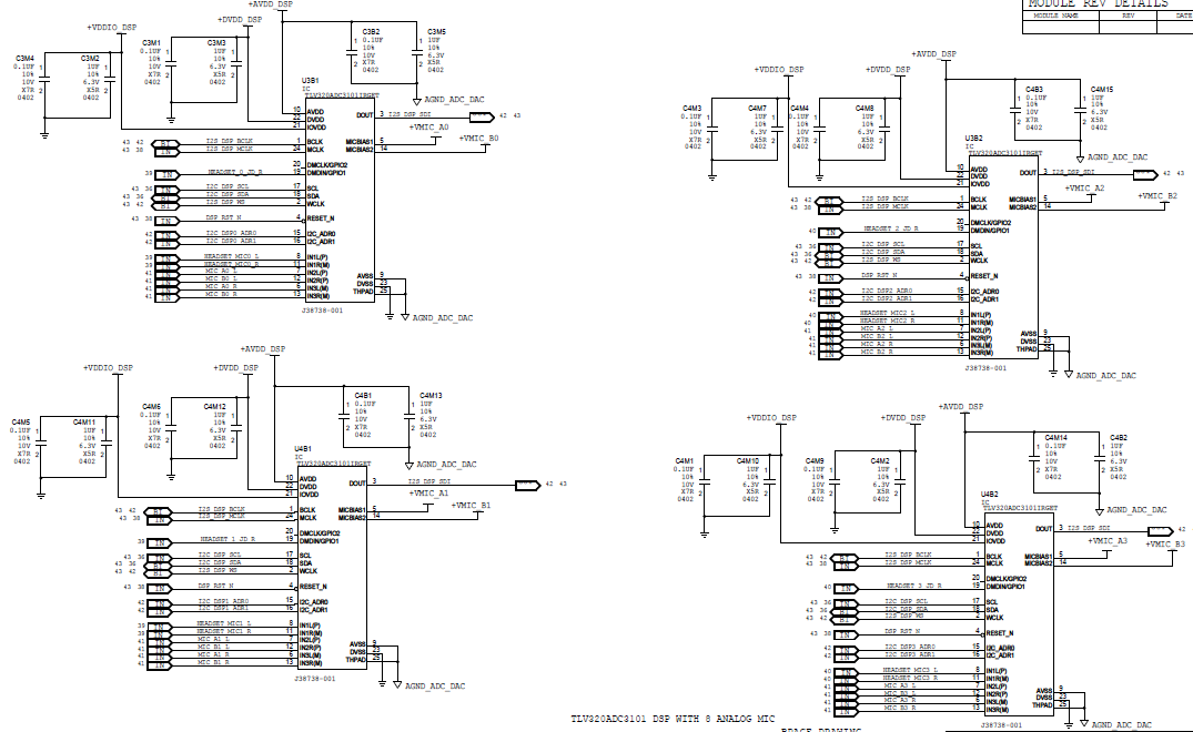
Giving you the background and current status


  1.             We are able to enumerate the ADCs.
  2.        I2C accesses are fine.
  3.      I2S accesses are fine.
  4.      Issue – We are seeing the AMIC output moving but we are not able to properly get it through ADC.
  1. So I need your help to get to know the right setting that we need to have.
  2. What are the setting that we need to follow for this MIC? 
  3. Now we have a maximum gain settings of 40db + 20db.

Thanks, 

Supritha

  • Hi, Supritha,

    I think that it is only necessary to configure correctly the ADC3101 registers. Please take a look at the following examples. These scripts can be used to configure the ADC3101 correctly. Please let me know if you have additional questions or comments.

    ###############################################
    # Recording an External Microphone Plugged into J9
    # ---------------------------------------------
    # ---------------------------------------------
    # For normal USB Audio, no hardware change is required.
    # If using an external interface, SW2.4 and SW2.5 of the USB-MODEVM must 
    # be set to HI and clocks can be connected to J14 of the USB-MODEVM.
    #
    # ADC3101EVM Key Jumper Settings and Audio Connections:
    # 1. Insert Jumpers W12 and W13 - mic bias
    # 2. Insert Jumpers W4 and W5
    # 3. Single-ended input IN1L(P)   - External Mic Plugged into J9
    #     Single-ended input IN1R(M) - External Mic Plugged into J9
    #  Note for a mono external mic both channels will contain the same audio data.
    ###############################################
    
    ###############################################
    # Software Reset
    ###############################################
    #
    # Select Page 0
    w 30 00 00
    #
    # Initialize the device through software reset
    w 30 01 01
    #
    ###############################################
    
    
    ###############################################
    # Clock Settings
    # ---------------------------------------------
    # The codec receives: MCLK = 11.2896 MHz,
    # BLCK = 2.8224 MHz, WCLK = 44.1 kHz
    ###############################################
    #
    # Select Page 0
    w 30 00 00
    #
    # NADC = 1, MADC = 2
    w 30 12 81 82
    #
    # AOSR = 128 (default)
    #
    ###############################################
    
    ###############################################
    # Audio Settings 
    ###############################################
    #
    # Default Setting: I2S, 16-bits, Slave Mode (BCLK and WCLK are inputs), 3-stating of DOUT disabled
    w 30 1b 00
    ###############################################
    # Signal Processing Settings
    ###############################################
    #
    # Select Page 0
    w 30 00 00
    #
    # Set the ADC Mode to PRB_P1 (default)
    w 30 3d 01
    #
    ###############################################
    
    
    ###############################################
    # Recording Setup
    ###############################################
    #
    # Select Page 1                                                     
    w 30 00 01			        
    #			        
    # Select MICBIAS1 = MICBIAS2 = 2.5V	        
    w 30 33 50
    #
    # Left ADC Input selection for Left PGA = IN1L(P) as Single-Ended
    w 30 34 fc
    #
    # Right ADC Input selection for Right PGA = IN1R(M) as Single-Ended
    w 30 37 fc
    #
    # Left Analog PGA Seeting = +25dB
    w 30 3b 32
    #
    # Right Analog PGA Seeting = +25dB
    w 30 3c 32
    #
    # Select Page 0                                                     
    w 30 00 00
    #
    # Power-up Left ADC and Right ADC
    w 30 51 c2
    #
    # Unmute Left and Right ADC Channels (Gain = 0dB)
    w 30 52 00
    ###############################################

    ###############################################
    # Line-In (J9) Stereo Recording
    # ---------------------------------------------
    # For normal USB Audio, no hardware change is required. 
    # If using an external interface, SW2.4 and SW2.5 of the USB-MODEVM must 
    # be set to HI and clocks can be connected to J14 of the USB-MODEVM.
    #
    # ADC3101EVM Key Jumper Settings and Audio Connections:
    # 1. Remove Jumpers W12 and W13
    # 2. Insert Jumpers W4 and W5
    # 3. Insert a 3.5mm stereo audio plug into J9 for
    #    single-ended input IN1L(P) - left channel and
    #    single-ended input IN1R(M) - right channel
    ###############################################
    
    ###############################################
    # Software Reset
    ###############################################
    #
    # Select Page 0
    w 30 00 00
    #
    # Initialize the device through software reset
    w 30 01 01
    #
    # Delay 100mS
    d 100
    ###############################################
    
    ###############################################
    # Clock Settings
    # ---------------------------------------------
    # The codec receives: MCLK = 11.2896 MHz,
    # BCLK = 2.8224 MHz, WCLK = 44.1 kHz
    ###############################################
    #
    # Select Page 0
    w 30 00 00
    #
    # NADC = 1, MADC = 2
    w 30 12 81 82
    #
    # AOSR = 128 (default)
    #
    ###############################################
    
    ###############################################
    # Audio Settings 
    ###############################################
    #
    # Default Setting: I2S, 16-bits, Slave Mode (BCLK and WCLK are inputs), 3-stating of DOUT disabled
    w 30 1b 00
    
    ###############################################
    # Signal Processing Settings
    ###############################################
    #
    # Select Page 0
    w 30 00 00
    #
    # Set the ADC Mode to PRB_P1 (default)
    w 30 3d 01
    #
    ###############################################
    
    ###############################################
    # Recording Setup
    ###############################################
    #
    # Left ADC Vol = 0dB
    w 30 53 00
    #
    # Right ADC Vol = 0dB
    w 30 54 00
    #
    # Select Page 1
    w 30 00 01
    #
    # Mic Bias Powered Down
    w 30 33 00
    #
    # Left ADC Input selection for Left PGA = IN1L(P) as Single-Ended
    w 30 34 fc
    #
    # Right ADC Input selection for Right PGA = IN1R(M) as Single-Ended
    w 30 37 fc
    #
    # Left Analog PGA Seeting = 0dB
    w 30 3b 00
    #
    # Right Analog PGA Seeting = 0dB
    w 30 3c 00
    #
    # Select Page 0
    w 30 00 00
    #
    # Power-up Left ADC and Right ADC
    w 30 51 c2
    #
    # Unmute Left and Right ADC Channels (Gain = 0dB)
    w 30 52 00
    

    Best regards,
    Luis Fernando Rodríguez S.

  •  
    We have totally 8 analog mics in our design using 4 ADC as shown below.
     
     
    But with your settings we are able to enable only on MiC on on2 ADC. Rest of the MICS are not working. Can you please help us in this ?
     
    Thanks & Regards,
    Supritha
     
  • Hi, Supritha,

    Are you connecting the ADCs in TDM mode? I mean, do all the ADCs share the same DOUT line (please take a look at the picture below for details)?

    If this is the case, you would need to ensure that the BCLK respects the following condition:

     You would require to add an offset and place the DOUT lines in Hi-Z when they are not in use. This is to avoid any collision between the ADCs DOUT lines. Please configure the Page 0 / Register 27 / Bit D0 as "3-stating of DOUT: enabled". Then, each ADC would need a particular offset to avoid any collision. In order to add an offset, please configure Page 0 / Register 28.

    Finally, which analog inputs would require at each ADC? The scripts that I shared use IN1L and IN1R as single-ended.

    Best regards,
    Luis Fernando Rodríguez S.