This thread has been locked.

If you have a related question, please click the "Ask a related question" button in the top right corner. The newly created question will be automatically linked to this question.

TLV320ADC3101: TLV320ADC3101 I2S Buffer/I2S Clock Settings

Part Number: TLV320ADC3101
Other Parts Discussed in Thread: TLV320AIC3254,

Hello,

I was wondering if there is any form of buffer for the TLV320ADC3101? I was hoping to buffer the values in the TLV and send the values in packets of size, say, 32 samples at a time. Is this possible, or is I2S data only available through streaming?

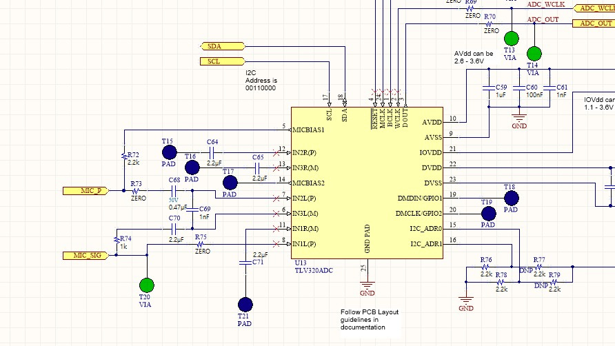
Also, how do I configure the clock settings that I want in PurePath Studios? I found that the initialization values in the header file that was generated from the GDE were associated with a sampling frequency of 44khz and I was hoping to have a sampling frequency of 8khz. I did try changing the values but was unable to read values from the I2S. I am not sure if this is because I am unsure of the settings of the I2S Tx or because of the settings of the I2S Rx.

Once the ADCs are enabled, is I2S set up for use? Also, is it possible to use only one ADC and stream only one ADC (e.g. only left ADC)? Would the values still be on one direction of the word select?

Any help would be great.

Thanks.

  • Hi, Nicole,

    Unfortunately, there's no buffer in the TLV320ADC3101. All the data is sent in samples from 16 to 32 bits via I2S. So, you would require another device such a microprocessor with I2S protocol which can be used to store the data sample by sample.

    Regarding your question about PurePath Studio, you would need to modify the sampling frequency in the properties window. Please click on the main window of PurePath Studio. You will see a properties window that contains different sample rates. Please place the correct sampling rate in "True" state and the rest of them in "False". Finally, ensure that 8KHz is selected as CurrentRate.

    PurePath Studio contains an initialization code that configures the PLL values depending of the CurrentRate. You may have access to this code by clicking on the ADC3x01 Framework. Its properties window contains a property called "SytstemSettingsCode". You may find all the register configuration there.

    The I2S is set once the ADC channels are enabled. You may configure each channel independently. As mentioned in the paragraph above, you may configure the register configuration with the SystemSettingsCode property. You would need to modify Page 0 / Register 81 (ADC Digital) to power down/up each channel.

    Please let me know if you have additional questions or comments.

    Best regards,
    Luis Fernando Rodríguez S.
  • Hello Luis,

    Thank you for all your answers.

    I still noticed that the comment on the PLL for the register initialization code says that it is for a rate of 88.2khz which is double of 44.1khz. I was wondering if it was just the comment that is not changed or if the code stays the same.

    Another thing is how do I know what the clock rate should be? I have read that the clock rate for the I2S should be 2*samplingFrequency*wordSelectPeriod, meaning if I were to want 16 bits for each data sample and a sampling frequency of 8khz, then I would have a clock rate of 512khz (word select period is twice the number of data bits if there are two channels). Is this correct?

    Thanks.3301.base_main_Rate8_pps_driver.h

  • Hi, Nicole,

    Thank you for your observation.

    It seems that the ADC3x01 Framework doesn't modify the PLL values when the rate is modified (some Frameworks have this function). In this case, you would need to modify the SystemSettingsCode depending of the MCLK (or CODEC_CLKIN clock) that you are using. Could you provide the MCLK, BCLK, WCLK and word length (16, 20, 24 or 32 bits) that you are using in your application? I may provide few PLL values recommendations.

    Regarding the clock rate, do you mean the BCLK? The BCLK is calculated as you mentioned:

    BCLK = (# channels) * (sampling frequency) * (Data bits)

    At least you should have a BCLK with this value or a multiple of this value.

    Best regards,
    Luis Fernando Rodríguez S.
  • Hello Luis,

    I am currently using an IDE that creates the clocks for me based on the input master clock. I am currently trying to program the TLV using the same values for P, R, K, etc. (based on the data sheet) and choosing the master clock from these values. I came with a master clock value of 1.024MHz. From this, the BCLK is 512kHz and the WCLK triggers every period of 32 bits (16 bits each channel).

    My biggest problem is that I have only been able to read values of 0 and was not sure if it was because of a problem with the clock or another initialization problem.

    Thank you very much for all your help so far.
  • Hello Luis,

    Another update on what I have tried. I tried changing the master clock to 1.024MHz (as mentioned in the comment before this). I am still getting values of 0 when reading the incoming value. I have also tried putting a TLV320AIC3254 framework object into PurePath just to see what values they use for P, R, K, etc. for an 8kHz sampling rate. I have also tried putting this in with a 4.096MHz clock. My values are still 0. I am not sure what the problem is or how I should approach it. I am sure that the microphone that is connected to the TLV is working properly. I am also sure that I can write/read from it through I2C.
  • Hi, Nicole,

    Is it possible to read all the registers of your TLV320ADC3101 application? Could you send me the registers values to determine if it is related with a configuration issue or anything else?

    Thank you.

    Best regards,
    Luis Fernando Rodríguez S.
  • Hi Luis,

    Here is the header file I am using. I tested writing a value and reading it back on I2C and it seemed to work.

    I just changed a few things in the header file: the PLL values, as stated before, and the input for each ADC (I tried putting all inputs in case we missed our mic).

    Thank you so much for you help.

    All the best,

    Nicole

    3632.base_main_Rate8_pps_driver.h

  • same problem here!!
  • Hi, Nicole,

    I reviewed your header file and it seems to be all in order. Could you verify if the analog inputs of the TLV320ADC3101 have a common-mode voltage when the registers are configured? Additionally, does your microphone require a bias level? The MICBIAS doesn't seem to be configured in the file that you shared (Page 1 / Register 51).

    Best regards,
    Luis Fernando Rodríguez S.
  • Hello Luis ,

    Our microphone does not require a bias level. Also, when viewing the analog inputs with an oscilloscope, we do see a waveform that oscillates around 0mV.

    Thanks,
    Nicole

  • Hi, Nicole,

    You should get a common-mode level at the analog inputs. This common-mode level is around 1.35V. Please ensure that the ADC blocks are powered on and the analog inputs are being routed to the PGA.

    Best regards,
    Luis Fernando Rodríguez S.
  • Hello Luis,

    How do I know if the ADC blocks are powered on? Is enabling the ADC blocks not sufficient? And would the routing to the PGA be internal? Please advise.

    Thanks,
    Nicole
  • Hi, Nicole,

    The ADC blocks should be powered on with Page 0 / Register 81. There is a flag register that may be used to ensure that the ADC is enabled (Page 0 / Register 36). Regarding the analog inputs routing, these are selected with Page 1 / Registers 52-57. You should get a common-mode voltage level once the ADC and the analog inputs are correctly configured.

    Best regards,
    Luis Fernando Rodríguez S.
  • Hello Luis,

    I can confirm that I am getting a common-mode voltage.

    Thanks,
    Nicole
  • Hi, Nicole,

    This means that the analog inputs are now ready to record the input signals. You only need to ensure that the I2S clock lines are correct. Then, you should be capable to record the signal via I2S.

    Best regards,
    Luis Fernando Rodríguez S.
  • Hello Luis,

    Please pardon the late response and thank you for your help thus far.

    Just to get an idea, how should the DOUT pin be behaving in general? At the moment, I see MCLK, BCLK, and WCLK are all getting clock inputs from the I2S master, but DOUT seems to always be set at 0. From my understanding, DOUT should be fluctuating based on the serial data it is outputting?

    MCLK = 512kHz

    BCLK = 256kHz

    WCLK = 8.192kHz

    Thanks,
    Nicole

  • Hi, Nicole,

    You are right. DOUT pin should show multiple pulses depending of the analog input voltage. You may test powering up only one of both ADCs. You should get DOUT pulses in WCLK low or high level.

    Best regards,
    Luis Fernando Rodríguez S.
  • Hi Luis,

    I have attached our setup for the TLV. MIC_SIG is the signal coming from our microphone. Would this configuration work?

    With this setup, I now tried enabling only ADC IN2L(P) as PLUS and IN3L(M) as MINUS ( page1/register52 set to 0x3f so IN2L and IN3L are differential inputs for the left ADC) and I enabled only the left ADC PGA and powered up the left ADC. I am still not getting any output through I2S nor am I seeing any changes on DOUT. I also have MICBIAS disabled for both MICBIAS1 and MICBIAS2.

    I remeasured IN2L and IN3L with an oscilloscope and found that they are both 1.3V.

    I tried enabling 3-state for DOUT and there still seems to be no pulse on the DOUT pin. I changed D0 in Page 0/Register 38 and D1 in Page 0/Register 27. Is this sufficient to set up DOUT 3-state? I just wanted to see if DOUT would show pulses. This is on page 15 of the datasheet (www.ti.com/.../tlv320adc3101.pdf )

    Thanks,

    Nicole

  • Hi, Nicole,

    When a differential microphone is in use, we recommend to connect it to a differential input as shown in the diagram below:

    In order to verify that the I2S communication and DOUT pin work correctly, you may try using the dither control register (page 1 / register 26). This register sends an offset value in 15mV steps. You should get constant digital pulses by configuring this register.

    Please let me know if the problem persists.

    Best regards,
    Luis Fernando Rodríguez S.

  • Hi Luis,

    I tried changing page 1 register 26 to 0x70 (should be 105mV on left channel) but I am still getting 0 for DOUT.

    You mention that I2S communication should work properly. Does that mean that the I2S buffer should never overflow and the samples are constantly being read?

    I also tried to change the pin to resistive pull up on the microcontroller side and it is visibly higher, than 0, if only slightly, but still is low enough to be considered as 0 so I suspect that there is something that is pulling DOUT to 0. Any ideas?

    Thanks,
    Nicole

  • Hello Luis,

    Is it possible to get some example code for an embedded system that uses the TLV320ADC3101? I was looking at the microphone example on the product page but did not find anything regarding the initialization of the TLV. Instead, I only found one I2C write that changed the volume. I am aware that there is a Linux driver available but I feel that this is not of much use to us.

    Any help would be appreciated. Thanks in advance.

    Nicole
  • Hi, Nicole,

    Do you have PurePath Studio installed in your PC? PurePath Studio can be requested at this site ( www.ti.com/.../aicpurepath_studio ). It may be used to configure a process flow and generate a .c and .h code to configure a host processor. Please take a look at the attached process flow. It is a basic configuration to get the microphone input at the I2S output.

    8080.ProcessFlow1.zip

    Please let me know if you require assistance with this process flow.

    Best regards,
    Luis Fernando Rodríguez S.

  • Hello Luis,

    I was finally able to get something from DOUT using one of the processing blocks. However, when I try to program the TLV with the miniDSP code, it no longer works. Do I need to write to all the pages on the miniDSP? I was deleting some of the pages that contained only 0 writes because it was causing memory problems on my microcontroller.

    Other things to note are that the voltage supply is stable and it is coming from the external LDO. Also, the PLL of the TLV seems to be working.

    Thanks,
    Nicole

  • Hi, Nicole,

    All the miniDSP registers are necessary to get a correct behavior. I would recommend to verify your miniDSP code with a simple algorithm. You may try with the process flow that I shared. Then, ensure that all the miniDSP registers are written correctly. Since you were able to get something from DOUT pin, the miniDSP code must be verified.

    Best regards,
    Luis Fernando Rodríguez S.
  • Hello Luis,

    Here is the header file that I am using. If I change the write to page 0 register 61 to 0x00, then it should read from the miniDSP and this is where the problem arises.

    The code below that is the miniDSP initialization code. I included all the page writes this time (before, I deleted some of the pages that were only writing 0s).

    I am still not getting any results on DOUT when trying to using the miniDSP.

    Thanks,

    Nicole1207.base_main_Rate8_pps_driver.h

  • Hi, Nicole,

    Could you provide the entire process flow of PurePath Studio? This is to test it on my evaluation boards and modify anything that could be wrong.

    Thank you.

    Best regards,
    Luis Fernando Rodríguez S.
  • Hi Luis,

    Here is the process flow. This is the process flow that you gave me to test, as well. It only has a volume control component in it. The only thing I changed in this package is the base_main_Rate8_pps_driver.h file for the first part of configuration.

    Thanks,

    Nicole

    2642.ProcessFlow1.zip

  • Hi, Nicole,

    The process flow works correctly on the TLV320ADC3101EVM-K. I just needed to configure the MICBIAS and increase the MICPGA in order to use the on-board microphone. Could you compare your application with the TLV320ADC3101EVM-K schematic? I'm using the WCLK and BCLK as inputs.

    www.ti.com/.../slau267a.pdf

    Best regards,
    Luis Fernando Rodríguez S.