This thread has been locked.

If you have a related question, please click the "Ask a related question" button in the top right corner. The newly created question will be automatically linked to this question.

TMS320F28069: Codec Setup

Part Number: TMS320F28069
Other Parts Discussed in Thread: TLV320AIC3104,

Hi All,

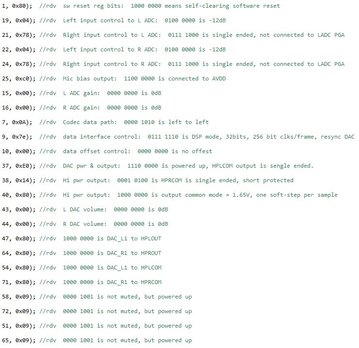
I've inherited a design that includes a TMS320F28069 MCU connected with a TLV320AIC3104 codec.  All is well with the product.  The codec is running at fs = 12kHz.

Now, I'd like to use this combination in a new design where the sample rate needs to be 24kHz.

Since the system was sampling fine at 12kHz, I never had the need to investigate how it was setup.  My assumption is that there is an initialization routine that is called from main() at bootup.  I suppose that routine sends info to the codec to set its sample rate select register values.  Past experience would have me believe this is a gross over-simplification of how it actually works, so I'm posting this message to see if anyone can shed some light on the subject.

Can someone please help me understand the sample rate setup procedure?

Thanks,

Robin

  • Hello Robin,

    I believe that this is a question for someone in the Audio Converters Forum so I am moving this post to that forum.

    Best Regards,
    Adam Dunhoft
  • Hi, Robin,

    In order to modify the sampling rate in our audio converters, it is necessary to take a look at the PLL and clock dividers registers. Since you were using a sub-multiple of 24KHz, it should be enough by modifying the Page 0 / Register 2. Just to ensure the correct register value, could you provide the actual registers configuration, please?

    Thank you.

    Best regards,
    Luis Fernando Rodríguez S.
  • Hi Luis,

    I'm not sure where to find the control register data. I don't see any setup happening in the initialization routines of the MCU code. The only thing I can find is the master clock. The processor has assigned a PWM to send the master clock signal to the codec. It's frequency was 3.072MHz. With no register configuration, I suspect that's how it's creating a 12kHz sample rate. I say that because Table 1 of slaa403 shows that 48 ksps is achieved with a 12.288MHz master clock. Therefore: 12.288MHz / 4 = 3.072MHz. Likewise: 48 ksps / 4 = 12ksps.

    Operating under that assumption, doubling the master clock frequency from 3.072MHz to 6.144MHz would effectively double the sample rate from 12ksps to 24ksps.

    Does that seem reasonable, or am I missing pieces from the puzzle?

    Thanks,
  • Hi, Robin,

    It is reasonable. However, this logic only works if the PLL is not used. If the frequency is increased and the PLL is used, one of the clock conditions couldn't be respected. You may try using 6.144MHz. If it doesn't work, it would be necessary to modify the register settings because the PLL would be in use.

    Best regards
    Luis Fernando Rodríguez S.
  • Hi Luis,

    I found the codec initialization routine.

    Page 0 / Register 2 has not been written to. Does that mean it is in a reset state, which places its value at 0x00? If so, then fs = fs/1, which is to say that there is no PLL rate change happening.

    Maybe the bit and word clocks have to be adjusted for the new sample rate?

    Thanks,
    Robin
  • Hi, Robin,

    Normally, the BCLK and WCLK are adjusted depending of the sampling rate. WCLK should be the same than the sampling rate (24KHz) and BCLK normally is suggested to be configured at the maximum useful frequency (64 * WCLK = 1.536MHz).

    Is it possible to modify this codec initialization routine. I may take a look at it to suggest some registers modification. Could you also provide the actual MCLK, BCLK and WCLK frequency values?

    Thank you.

    Best regards,
    Luis Fernando Rodríguez S.
  • Hi Luis,

    MCLK is now 6.144MHz, BCLK is 1.536MHz, and WCLK is 24kHz.  My goal is to run it at a sample rate of 24kHz, so I think I'm either there or getting close.

    I'm a little confused about MCLK.  When the project was given to me, MCLK was 3.072MHz.  The sample rate was 12kHz, and I assumed 3.072MHz was chosen to provide a 12kHz sample rate.  Is this a common way to get a 12kHz sample rate?

    If not, what should MCLK be and how would I go about changing the sample rate from 48kHz to 24kHz?

    Thanks,

    Robin

  • Hi, Robin,

    If the PLL is disabled, this clocking configuration will work perfect. Could you verify Page 0 / Register 3? Is D7 bit enabled? If it is not enabled, you may proceed with these values.

    Basically, 12.288MHz is used as default MCLK value to get 48KHz without need to configure PLL and dividers settings. If 6.144MHz is used with the default settings, you should get 24KHz sampling rate. However, if PLL is used, it won't give the same results.

    You may find more information about the clocking settings on the clock generation section and the document below:

    www.ti.com/.../tlv320aic3104.pdf
    www.ti.com/.../slaa403.pdf

    Please let me know if PLL is disabled. Otherwise, could you provide the init file to suggest new PLL values?

    Thank you.

    Best regards,
    Luis Fernando Rodríguez S.
  • Hi Luis,

    Page 0 Register 3 has not been initialized by any code, so it is in its default reset state.

    Here is an image of the initialization code that I found:

    The number to the left of the comma represents the register number and the hex number is the value placed in that register.  All are page 0.  The comments are my notes while deciphering it.

    So, it seems like the PLL is not in use, therefore my settings are correct for using it at a 24kHz sample rate.

    I'll take a look through the app notes you sent.

    Thanks for your help, I think this one is solved.