This thread has been locked.

If you have a related question, please click the "Ask a related question" button in the top right corner. The newly created question will be automatically linked to this question.

TPA3116D2: High pop on turn-on from SD

Part Number: TPA3116D2

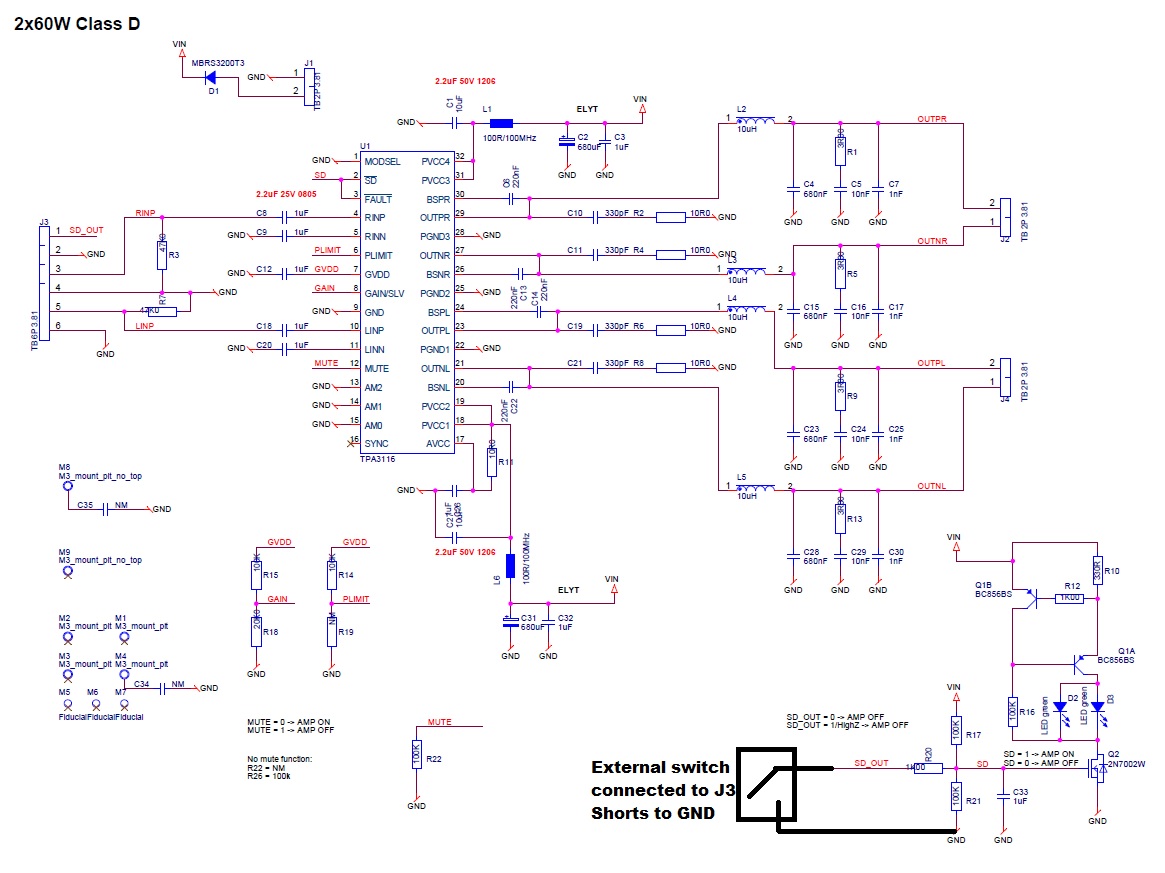
I'm currenly doing a TPA3116 setup, but I am experiencing a rather high pop during turn on via SD.

My SD is done through a external switch, which pulls the SD to GND via 1k and pulled high with 100k to VDD. A 1uF cap is placed on SD pin which the 100k has to charge. Please see schematic. 

  • Hi Casper,

    Thanks for asking questions in E2E. Most of the pop issues are caused by the input portion design. Could you please try the following suggestions:

    1. The proper procedure for power-on is as following. Unmute is enabled after SDZ is pulled up(in Stage3 and Stage4). The delay needs to be larger than 40ms. In this way, the outputs are in MUTE during the sett up on input.

    2. From the SCH, you are using single-ended input mode, the pop performance would be a little worse than differential mode. Please check the input signal path, and make sure the load on the P and N input are the same, else pop could be caused during power up. 

    Best regards,

    Shawn Zheng

  • When I enable the IC via SD pin, the following POP is seen on both outputs and they are identical. The output goes negative towards rail voltage (in this case 12V). Why does this happen? Should my input resistors be lower e.g. 10k? 

    On the scope, my positive probe is connected to R+ (or L+) and the R- is connected to the "GND" of my differential probe.

  • UPDATE!
    I have just tested with my PC connected to the AUX (normal mobile phone) and the POP is gone.. I think there is something wrong with my mobile phone and therefore I see this POP.
    The POP is still there if there is nothing connected to the input however...
  • If I reduce the input resistor to 2k (from 47k) then the pop goes from 12V to 5V. And at 1k it goes to 2.5V.. And this is at otherwise open end input. So maybe the input should be around 220R..?
  • Hi Casper,
    Thank you very much for sharing the update.
    Sorry for the confusion. The #2 suggestion which I wrote above means that the signal path on the differential input (INN, INP) should match in signle-ended input mode. There are one 47KOhm resistance and one 1uF capacitor on the INP, but there is only one 1uF capacitor on the INN. I think you can try to remove the resistance. If that resistance is necessary for the input, then you can use MUTE pin to erase the pop (#1 suggestsion).
    Best regards,
    Shawn Zheng
  • Hi Shawn,

    OK so you believe that the pop is due to the RC of 47k and 1uF while on the negative, there is nothing? And by that, the pop will last until the RC is charged on the P, because it's precharged on the other side of the 1uF (IC side) to about 3V? Thereby we get a difference in impedance and when there is a difference in impedance and the precharge, we will get the pop since the two voltages won't come up at the same speed?

    I thought the 47k would help me to get rid of humming etc. because the output in some occasions was not "loaded"/pulled to GND.

    I'll try to remove the 47k (now 220R) and see what happens :-) More info later.
  • OK.. here's the thing.. As stated, the RC is doing everything bad. If I remove the 47k there is no pop :-)

    I tried to simulate the input stage and by doing that, I can see it's the 47k which is the problem. There is almost no pop with 220R (which I also measured) and I'f I remove (1G Ohm) the resistor, the signal is also OK..

    I then removed the 47k from the PCB and the problem seems to be gone.. wil ltry with speakers attached later, but on the oscilloscope, I didn't see anything popping.

  • Hi Casper,
    Great work! I think you could enjoy the beautiful music now. :)