This thread has been locked.

If you have a related question, please click the "Ask a related question" button in the top right corner. The newly created question will be automatically linked to this question.

TPA3110D2: apparent failure at 24V

Part Number: TPA3110D2
Other Parts Discussed in Thread: TPA3111D1

Dear Support,

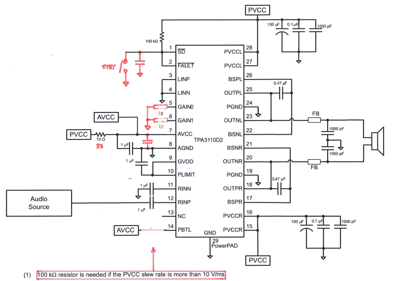
I am using the TPA3110D2 on a preassembled board that implements a configuration very similar to the datasheet example of single-ended input with PBTL output. The supply voltage is 24V, which I believe should be OK as the IC and board are rated for up to 26V.

I am seeing a fault where the device operates fine once only, then when power is removed and reapplied it no longer works (audio silent, low power dissipation). It seems that pin 7 (AVCC) now has low impedance to ground (internal IC failure) and this then causes high current to flow in the 10 ohm resistor feeding this pin from the 24V supply, causing failure of this resistor or high dissipation in the IC. The power supply is a commercial 24V SMPSU and checks out OK.

Is it safe to operate this IC at 24V? What could be the cause of such damage?

Thanks!

Trinity

  • Hello Trinity! Shawn will be able to help you with the details of your question, but I also have a couple of questions for you. As you are operating PBTL, I assume you may be driving a mono solution? If so have you also looked at our mono TPA3111 version: www.ti.com/.../TPA3111D1. Also, its not clear to me what load you are driving and to what the gain may be set per section 10 of the DS. We just want to make sure it is not being driven to shutdown. Thanks, Jeff
  • Hi Trinity,

    TPA3110D2 can work with 24V power supply without any problem. And under normal circumstances, the current for AVCC is very small (around 10mA). So apparently, the device is not working normally.

    As Jeff said, it's a good to check TPA3111D1 EVM SCH, which is a very similar application as yours. Could you please show me your SCH? Is it possible a ESD issue or solding issue?

    Best regards,

    Shawn Zheng

  • Hi Shawn and Jeff,

    Thanks a lot for your response! I was not aware of the mono variant. I've traced out the schematic and it is almost identical to the datasheet PBTL example (gain set to 20dB), but with some differences marked here in red:

    I noticed a couple of points that might be relevant:

    i) The 100k series resistor for PBTL is omitted and the pin is tied directly to AVCC. The PVCC slew rate is determined by the charge time of the PVCC capacitance (total 400uF for me), and for a line impedance of 1 ohm from the power switch I calculate it can exceed 10V/ms with a supply of 24V. Could this cause failure of the IC?

    ii) The /FAULT output is coupled to ground with a capacitor and there is an optional jumper also connecting to ground (left open). Can this output tolerate a short to ground?

    Finally, these boards are coming from China, and I did consider the possibility that they may contain fake parts. Are you aware of any fakes? The quality of the boards themselves is rather poor. Here is a photograph of the device:

    Thanks again for your rapid and helpful support!

    Regards,

    Trinity

  • Hi Trinity,

    The 100k series resistor for PBTL is used to protect this pin if PVCC slew rate is too high. If PBTL pin is damaged, the device could work in PBTL mode or BTL mode or even unknown mode. If it works in BTL mode, OC fault will be triggered because the OUTPL and OUTNL are connected together (the same as OUTPR and OUTNR). So basically this resistor is necessary in an application. 

    And, connecting FAULT pin to GND will not damage the device.

    I think you could solder a good device first and see if the issue is still there. If yes, we will continue looking for the possible application issue on this board.  

    Best regards,

    Shawn Zheng