This thread has been locked.

If you have a related question, please click the "Ask a related question" button in the top right corner. The newly created question will be automatically linked to this question.

PCM3070: PCM3070 without an EVM, PPS code not working

Part Number: PCM3070
Other Parts Discussed in Thread: TPA3118D2

Hi All!

I've been experimenting with the PCM3070 CODEC with miniDSP. I don't have an EVM, but instead, I designed my own test board that includes a TPA3118D2 analog class-D amplifier. Without an EVM, I'm not able to test the Control Software or PurePath directly, but to manually program and configure registers using an MCU and the I2C bus. My setup includes an onboard 24,576MHz oscillator tied to MCLK pin.

- The analog bypass path works properly (no need to program coefficient/instruction memory)

- The mixer amplifiers bypass path works properly (no need to program coefficient/instruction memory)

- When using processing blocks in both ADC and DAC, instead of the miniDSP (configuring reg[0][60] and reg[0][61]), the data path works properly with some non-trivial adjustments: setting WCLK and BCLK as outputs, using BCLK_N divider and setting the loopback control "Stereo ADC output is routed to Stereo DAC input" in reg[0][29], and of course, setting proper values for the PLL to work for a 44.1KHz sampling rate.

- NOT WORKING: When using the miniDSPs for signal processing, PurePath must be used to generate the required coefficients/instructions for both miniDSP cores, according to the designed process flow. By using the Build->Generate Code option, PPS generates the .h file driver that I append to my MCU code. When booting the PCM3070 code with the PPS code, the codec only outputs a loud noise (not the 60Hz hum noise mentioned in another thread, I'm using a stereo differential output) in both channels.

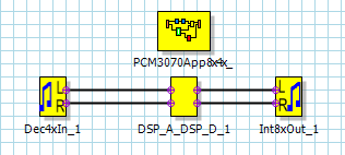
Here's my simple test process flow:

Here's a screenshot of the differential outputs of one channel, centered around a common mode voltage of 0.9V:

I can change the DAC volume (the noise volume), but by testing several register configurations, I can't manage to send proper ADC data to the DAC input when using the miniDSP cores. Thus, Im not able to use PPS to load any desired process flow.

Is there something that I'm missing? I've tested an EQ example included in sompe other PCM3070 thread, and also the SoundBar process flow (with the proper input and output routing configuration) but no success...    Has it happend to someone else?

I append the configuration file used, generated by PPS and formatted for my MCU code.

pps_driver_01_reconfigured.h

I highly appreciate any help.

  • Hi, Jose,

    Welcome to E2E, Thanks for your interest in our products!.

    From your comments, it seems that the problem could be related to the configuration of the device in PurePath Studio (PPS). When a new PPS block diagram is created, the configuration of the device (like input and output routing, PLL, clocks, GPIOs, etc) should be loaded into the framework by updating the System Settings Code. You can access this code by selecting the framework, the code should be available in the properties window. You need to update the code with the proper device configurations. I would recommend you to verify if the system settings code that is loaded by default  is compliant with your system, if not, please try updating the required settings. 

    Best Regards,

      -Diego Meléndez López
       Audio Applications Engineer

  • Thanks Diego!

    I've been around this problem for quite a while, so sitck with me. I'll try to explain all that I've done:

    When generating the code, PPS organizes the code in 3 structre arrays: REG_Section_program, miniDSP_A_reg_values and miniDSP_D_reg_values. The System Settingd Code Editor is used to modify ONLY the REG_Section_program, since it contains the general CODEC configuration. I've tried 2 things: 

    • Editing directly with the System Settings Code Editor, the registers needed, and then generating the driver code.
    • Generating the complete code without editting anything in the System Settings Code editor, and editting the generated code outside PPS, with a plain text editor.

    In both cases I get the same result. (( a small parenthesis: the default System Settings Code that PPS generates includes register "reg[  1][ 51] = 0x40    ; Mic Bias enabled, Source = Avdd, 1.25V". According to the datasheet register map, and the application reference guide, that register is reserved, and should not be used)).

    Here's a summary of the registers I've configured and tried loading to the PCM3070 both inside PPS and outside (all of them described and commented in the .h file appended before):

    • Power Init, LDO, AVDD and Common Mode voltages - Verified by measuring CM voltages and LDO.
    • Interpolation, Decimation, IDAC, IADC, Adaptive filtering, miniDSP for signal processing
    • PLL and clock generation (I use the PLL and the GPIO pin to test the sampling frequency, which appears to be OK at 44.1KHz) - Verified when using the process blocks instead of the miniDSPs
    • PGAs routing, Mixer amps, Output power amps routing (HPL, HPR, LOL, LOR) - Verified by testing different paths and using the analog bypass and mixer amps bypass
    • DAC power, unmute, volume - Verified by reading the DAC state flags
    • ADC power, unmute, volume - Verified by reading the ADC state flags

    I don't use DRC, AGC nor Adaptive filtering. As I said, I have confidence that all these configurations are OK since I've tested them in one or another way.

    May PPS be generating some buggy code? the version that I got is: Version 5.95 build 1 revision 35815, Component library version 6226. In the components library I'm only able to choose between PCM3070 and PCM51XX frameworks.

    I also want to say that the Audio Serial Interface Multiplexing scheme (shown in the Application Reference Guide) is confusing to me:

    What I've drawn in colours Red and Green are just regular paths for the Audio Interface colcks. But the blue path multiplexer gives me no option to avoid sending input data to the Audio Digital Serial Interface. In my test application, my goal is to receive the ADC data, process it and send it to the DAC. I don't have an external audio serial data bus. I think it could be some weird configuration missing here.

    Again, thanks for any advice. I keep going around to see if I find any solution.

  • Hi Diego!

    good news out here!.

    Finally I figured out what was happening. I've had no time to test it in more detail, but it turned out to be the miniDSP_D_Cycles and miniDSP_A_Cycles parameters (which translate into the IDAC and IADC register values): I had been using the default ones automatically selected by PPS (IADC = IDAC = 904). I also tried the value of 1000, which is the value shown in the SoundBar example.

    I found this link from the AIC3254 wiki documentation, that states that they are the "number of cycles allocated per word clock frame". It is not very clear to me what that implies. It also relates it to the power consumption (more cycles, more current consumption). And gives this relation: IDAC>=MDAC*DOSR and IADC>=MADC*AOSR. I thought I was in the safe side, since in my case IDAC(904) >= MDAC(3)*DOSR(128), and the same for IADC. With these values, my setup never worked. The same post points to this other wiki about power control configuration of both miniDSP cores. It also says: "The user must program IADC = IDAC = MDAC*DOSR = MADC*AOSR", and gives some guidelines for power sequencing of ADC and DAC. Once I reprogrammed IDAC and IADC with the value 384, it worked nicely!.

    So, I'm happy to get it working now, and 'till now I've not tested it using different IDAC values, but I'm still confused about the implications of this value. I know that there should be an integer mulpiple of the Decimation/Interpolation factor (whatever be the case), but appart from that, I'm not understanding what are the rules to choose those values. So I would ask for a little guidance about it.

    Thanks a lot!

  • Hi, Jose,

    Sorry for this confusion. Actually, there's a mistake in the wiki article that you mentioned. The correct statement is:

    IDAC <= MDAC*DOSR and IADC <= MADC*AOSR

    So, you should get a correct codec behavior if these conditions are respected.

    Best regards,
    Luis Fernando Rodríguez S.