This thread has been locked.

If you have a related question, please click the "Ask a related question" button in the top right corner. The newly created question will be automatically linked to this question.

TLV320AIC3104-Q1: Cellular+stereo headset connection, unused analog inputs

Part Number: TLV320AIC3104-Q1
Other Parts Discussed in Thread: TLV320AIC3104

Hello!

I have two questions I'm hoping you guys could help me with. 

I'm working on a prototype to enable eCalls to be made from vehicles. I've looked at the various eCall reference designs provided by Texas Instrument and have zeroed in on the TLV320AIC3104. Since this is only a prototype, I'm trying to use a Stereo+Cellular headset instead of the recommended two audio jacks for mic and speaker separately. 

I found the slaa454.pdf document, where the following connection is recommended. 

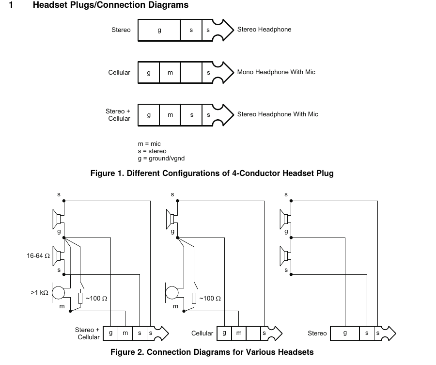
I've used this reference in addition to the information provided from the datasheet of the 320AIC3104 as well the  320AIC3104 evaluation board datasheet. 

This is the final schematic I've come up with 

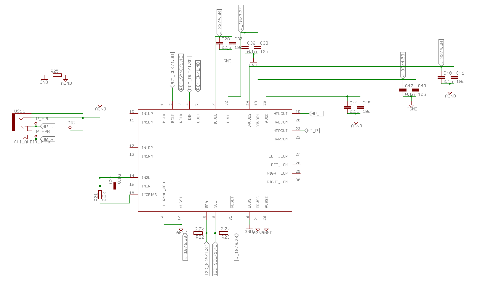
My first question is, have I got the headset jack connections right? Do you see any possible problems there? 

Second question is what to do with the unused analog inputs ? Can I leave them as they are or do I tie them to ground with a 0.47uF Capacitor as recommended? If yes, then what package size is recommended?

Thank you for your help!

  • Hi, Pradeep,

    Welcome to E2E and thank you for your interest in our products!

    I have few comments about your schematic. Please take a look at them and let me know if you have additional questions or comments:

    - The headset detection has two configuration modes: the pseudo-differential (capacitor free) and the AC-coupled. In case of pseudo-differential mode, it requires to use the HPRCOM and HPLCOM ( www.ti.com/.../tlv320aic3104.pdf ). These pins fix the common-mode voltage at the outputs. By other hand, the AC-coupled mode requires of capacitors at the outputs ( www.ti.com/.../tlv320aic3104.pdf ). I would recommend to add the capacitors at the headphone outputs as shown in figure 26. 47uF is the suggested value.

    - Regarding the unused analog inputs, I would recommend to connect them to a 0.47uF capacitor to GND. We don't have a recommended package size. So, you may select the best package based on your PCB requirements.

    Best regards,
    Luis Fernando Rodríguez S.
  • Hello Luis,

    Thank you for your work on this forum! I've found a number of your posts really helpful!

    Please find attached the new schematic for the audio codec. 

    I've also added a 0.1u Capacitor and 10k resistor to the RESET for power up reset. 

    Regarding your statement about TI not having recommended package size for capacitors, would you suggest it makes no difference whether I use 0402 Capacitors or 0603 Capacitors?

    The datasheets of these capacitors shows different impedance values at different package sizes even though they have the same capacitance value.

    For example, looking at the 0.10µF Capacitors from Murata

    0402 size

    0603 size

    Should this be taken into account? Or is this irrelevant since frequencies shown here are extremely high?

  • Hello, Pradeep,

    It is good to know that our posts are really useful. Thank you for your feedback. I additionally recommend to take a look at our wiki page ( e2e.ti.com/.../ ). Particularly, I recommend to take a look at this wiki article, it contains useful information regarding the audio codecs ( e2e.ti.com/.../3377.common-noise-issues-in-codecs ).

    Thank you for providing the frequency characteristics tables. However, I don't see any inconvenience in using any of these packages sizes. As you mentioned, it is irrelevant since the frequencies shown are too high.

    Best regards,
    Luis Fernando Rodríguez S.