This thread has been locked.

If you have a related question, please click the "Ask a related question" button in the top right corner. The newly created question will be automatically linked to this question.

TLV320ADC3101: Problems with I2S communication with TLV320ADC3101

Part Number: TLV320ADC3101

Hello everyone,

I am trying to read in data from two digital PDM mics via the TLV320ADC3101 and send the decimated PCM-data to a microcontroller via I2S. Unfortunately I am not getting any signals on my I2S Bus.

My configurations are the following:

  • BCLK = 512kHz, I want to read in 2*16bit (L/R) =32bit -> WCLK=16kHz
  • I am using BCLK as CLK for the TLV320. Therefore, I use the PLL with P=1, R=4, J=40, D=0000 (to meet all requirements from the data sheet from the CLK calculation examples) and divide by 40 (using NADC =40 and MADC=1) to get 2.048 MHz at the DMCLK output. (This works so far)
  • The read data from the digital Mics should be decimated by 128 (AOSR=128, Processing block= PRB_R1) to get a sampling rate of 16kHz.
  • I have used the default configuration for the ADC audio interface control 1 register (Reg27) (I2S, 16bit, BCLK=input, WCLK=input, 3 stating of DOUT=disabled) and the DOUT Control Register (REG53) is also default (Bus keeper=disabled, DOUT=primary DOUT output for codec interface)
  • ADC IADC Register (REG21) is also at default = 128

Questions:

  1. Am I missing anything to enable the I2S output via DOUT or do I have a fallacy when calculating WCLK?
  2. Does the miniDSP Engine Decimation Ratio (REG22) anything when using a processing block? (I am just a little bit confused because as I understood it, I set the decimation rate with AOSR=128.)

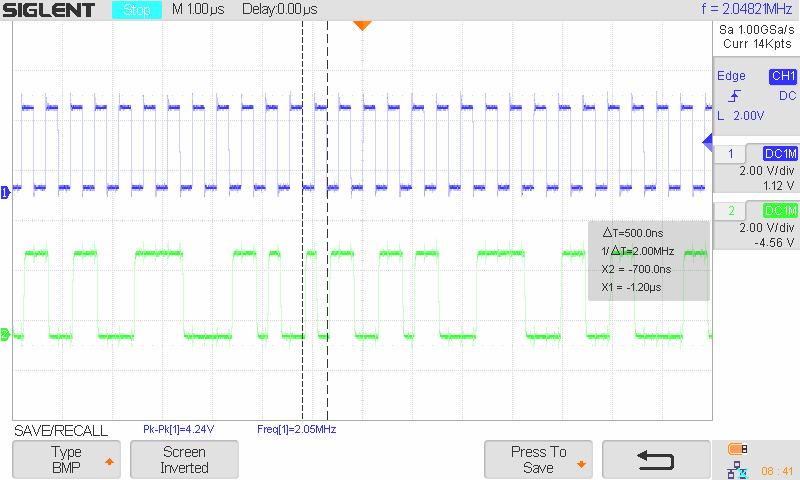
Attached is an image of my current I2S communication (Blue=WCLK, Green=BCLK, Red=DOUT/I2SData)

I would really appreciate any help :-)


  • Hi, Mike,

    Welcome to E2E, Thanks for your interest in our products!.

    In order to use the digital mic input (PDM) for the TLV320ADC3101, you need to configure the digital mic as the source for each ADC channel. This is done by writing a '1' to bits D2 and D3 of register 81.  Can you please try this?. Also, is the digital microphone streaming data to the 'ADC3101? 

    Regarding the decimation ratio, when using one of the processing blocks, there is no need to change registers 21 and 22, so it is recommended to keep them with the default value. These registers are only effective when using the programmable miniDSP. 

    Best Regards,

      -Diego Meléndez López
       Audio Applications Engineer

  • Hi Diego,

    Thank you for your fast reply!

    I have already set the register 81 to 0xCE and the microphone is delivering data as you can see in the attached file (blue=clk with 2.048MHz, green=pdm data from 2 mics) but I still get no I2S Data.

    I thought maybe there is something wrong with the used BCLK (512kHz) and WCLK (16kHz) BCLK/WCLK=32 (= number of bit to be send; 16bit*2) because in the data sheet example BCLK/WCLK=64 is used  (again sending 16bit*2).  Could this be the problem?

    Regarding to the decimation, ok then I just set the AOSR register to 128 and leave the other registers (21 and 22) at their default value. 

    Maybe my I2C configuration of the TLV320 helps somehow:

    • (PAGE0, 0x00);           //Select Register Page 0
    • (0x01, 0x01);               //Software Reset

    • (REG04_CLK_GEN_MULTIPLEX, 0x07);  //Set BCLK as PLL input
    • (REG05_PLL_P_AND_R_VAL, 0x14);       //Enable PLL, Set P=1 R=4
    • (REG06_PLL_J_VAL, 0x28);                        //J=40
    • (REG07_PLL_D_VAL_MSB, 0x00);            //D=0
    • (REG08_PLL_D_VAL_LSB, 0x00);             //D=0
    • (REG05_PLL_P_AND_R_VAL, 0x94);       //Start up PLL
    • delay(10); //ms
    • (REG18_NADC_DIV, 0xA8);       //N=40
    • (REG19_MADC_DIV, 0x81);       //M=1
    • // (REG20_AOSR, 0x80);             //AOSR=128 -> default

    • // (REG27_AUDIO_INTERFACE1, 0x00);          //->default
    • (REG51_DMCLK, 0x28);                                      //Set DMCLK as CLK-Output for DigiMic
    • (REG52_DMDIN, 0x04);                                       //Set DMDIN as Data-Input for DigiMic
    • // (REG53_DOUT, 0x12);                                      //->default
    • (REG61_PROCESSINGBLOCK, 0x01);           //Set PRB_R1
    • (REG80_DIGIMIC_POLARITY_SEL, 0x02);    //Capture Left-Channel (L) on falling and Right-Channel (R) on rising edge
    • (REG81_DIGIMIC, 0xCE);    //Turn on ADC channel(L&R); Set DATA Input to DMDIN (L&R); Enable DigiMics (L&R); Disable volume control soft stepping
    • (REG82_ADC_CHANNEL_MUTE, 0x88);        //Unmute

    I really appreciate our help!

    Best Regards,

    Mike

  • Hi, Mike,

    Thanks for the detailed feedback. The configuration code you provided is very helpful, the device seems to be configured correctly and the clocks should be OK. However, it seems you are not unmuting the ADCs as register 82 is configured to mute both ADC channels. Can you please try unmuting the channels by writing a 0x00 to Register 82?

    I verified that the configuration and behavior of the device is correct by using your code (once unmuted) in the EVM under the given clock conditions. 

    Best Regards,

      -Diego Meléndez López
       Audio Applications Engineer

  • Hi Diego

    Thank you very much! With your help I managed to get the TLV320 working. I knew it was just one register which was written wrong, but could find it by myself. J

    I have one more question. As I understood it from the datasheet it is possible to power down the ADC of the TLV320 if just digital mics are used. Does that mean that the AVDD connection to 3.3V is not needed or does it mean that I still need the AVDD and the ADC is just power down via the register configuration?  

    Best Regards,

    Mike

  • Hi, Mike,

    The mention for the datasheet is referent to the ADC being powered down via register setting. AVDD is required for the internal analog blocks of the device, so it should be powered at all times. 

    Best Regards,

      -Diego Meléndez López
       Audio Applications Engineer