This thread has been locked.

If you have a related question, please click the "Ask a related question" button in the top right corner. The newly created question will be automatically linked to this question.

TLV320AIC3104: I use the TLV320AIC3104 revice IIS signal , afther the mcu initialize Before the Android System starting, there are noise output in headphone about 2.5s .

Part Number: TLV320AIC3104
Other Parts Discussed in Thread: TLV320AIC31

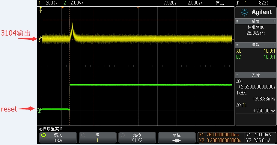
I use the TLV320AIC3104 revice IIS signal , afther the mcu initia19_Audio Codec.pdflize Before the Android System starting, there are noise output in headphone about 2.5s .

  • Hi, Andrew,

    Welcome to E2E and thank you for your interest in our products!

    Could you provide more details about this? Could you provide the registers configuration? Additionally, do you have captures about the noise output? Could you provide the clock values (MCLK, BCLK, WCLK)?

    Best regards,
    Luis Fernando Rodríguez S.
  • we test the reset signal , when the reset from low to high there is noise ,the picture is the captures

  • Hi, Andrew,

    Which output are you measuring? Is the yellow signal associated to an analog output pin? When an analog output is measured with the scope, you require a low-pass filter as described in the document below:

    www.ti.com/.../slaa313.pdf

    Our audio codecs generate out-of-band noise that is measured with the scope as you shown in your picture.

    Best regards,
    Luis Fernando Rodríguez S.
  • Dear

    Thank you for your help !

    Test the  3104  PIN19 and pin23, output ,

    the register configuration and init as below , if there is any not clear ,please ask me ,many thanks  !

    right now  the most issue is the noise when the system starting .

    void tlv320_DrvInit(void)

    {

        HI_ERR_AIC3X("tlv320_Init\n ");


        tlv320aic31_write(I2C_AIC31, 0x1, 0x80);

        time_delay_us(50);

    #if 0

        /* Mclk =27M,use PLL mode*/

        tlv320aic31_write(I2C_AIC31, 102, 0xc2);

        tlv320aic31_write(I2C_AIC31, 3, 0x82);  //set p=2

        tlv320aic31_write(I2C_AIC31, 4, 0x1c);  //set j=7

        tlv320aic31_write(I2C_AIC31, 5, 0x2c);

        tlv320aic31_write(I2C_AIC31, 6, 0x8 );  //reg5 and reg6 set d=2818

        tlv320aic31_write(I2C_AIC31, 11, 0x1 ); //set r=1


        tlv320aic31_write(I2C_AIC31, 2, 0x00);  //FS=Fsef/6=8khz

    #else

        /* Mclk = 12.288M,not PLL mode*/

        tlv320aic31_write(I2C_AIC31, 102, 0x32); //if pll,p=r=1,k=8

        tlv320aic31_write(I2C_AIC31, 101, 0x01);

        tlv320aic31_write(I2C_AIC31, 3, 0x10);


        tlv320aic31_write(I2C_AIC31, 2, 0x00);


        //tlv320aic31_write(I2C_AIC31, 10, 0x08);

    #endif


        tlv320aic31_write(I2C_AIC31, 8, 0x30);


        //tlv320aic31_write(I2C_AIC31, 8,  0x20);

        tlv320aic31_write(I2C_AIC31, 9, 0x27 );  //16bits

        //tlv320aic31_write(I2C_AIC31, 15,  0xc );

        //tlv320aic31_write(I2C_AIC31, 16,  0xc );

        tlv320aic31_write(I2C_AIC31, 12, 0x50);  //0 means disabled

    #ifdef BOARD_TYPE_fpga

        tlv320aic31_write(I2C_AIC31, 25, 0x0 );

    #else

        tlv320aic31_write(I2C_AIC31, 25, 0x80 ); // enable mic bias

    #endif

        tlv320aic31_write(I2C_AIC31, 17, 0xf );

        tlv320aic31_write(I2C_AIC31, 18, 0xf0);

    #if 1

        tlv320aic31_write(I2C_AIC31, 15, 0);

        tlv320aic31_write(I2C_AIC31, 16, 0);

    #ifdef BOARD_TYPE_fpga

        tlv320aic31_write(I2C_AIC31, 19, 0x7); //0x7, ena left adc

        tlv320aic31_write(I2C_AIC31, 22, 0x7); //0x7, ena right adc

    #else

        tlv320aic31_write(I2C_AIC31, 19, 0x07); //left adc single_end mode, 0dB volume; ena power

        tlv320aic31_write(I2C_AIC31, 22, 0x07); //right adc single_end mode, 0dB volume; ena power

    #endif

        tlv320aic31_write(I2C_AIC31, 28, 0);

        tlv320aic31_write(I2C_AIC31, 31, 0);

        tlv320aic31_write(I2C_AIC31, 26, 0x00);

        tlv320aic31_write(I2C_AIC31, 29, 0x00);

    #else

        tlv320aic31_write(I2C_AIC31, 19, 0x4 ); //differential input;Input Level Control(not attenuation);adc power

        tlv320aic31_write(I2C_AIC31, 22, 0x4 );

        tlv320aic31_write(I2C_AIC31, 26, 0x95); //AGC abled;set Target Gain,Attack Time,Decay Time(medium)

        tlv320aic31_write(I2C_AIC31, 27, 0xc0); //input gain control(max (enlarge,adjust value level))

        tlv320aic31_write(I2C_AIC31, 28, 0x2 ); //Hysteresis and Clip disabled;Noise Threshold Control

        tlv320aic31_write(I2C_AIC31, 29, 0x95);

        tlv320aic31_write(I2C_AIC31, 30, 0xc0);

        tlv320aic31_write(I2C_AIC31, 31, 0x2 );

        tlv320aic31_write(I2C_AIC31, 34, 0x0 ); //debounce control

        tlv320aic31_write(I2C_AIC31, 35, 0x0 );

    #endif


        //tlv320aic31_write(I2C_AIC31,27,0xfe);//input gain control(max (enlarge,adjust value level))

        //tlv320aic31_write(I2C_AIC31,28,0x0);//Hysteresis and Clip disabled;Noise Threshold Control

        //tlv320aic31_write(I2C_AIC31,30,0xfe);

        //tlv320aic31_write(I2C_AIC31,31,0x0);


    #ifndef BOARD_TYPE_fpga

        tlv320aic31_write(I2C_AIC31, 7, 0xa); //set Fsref;dual rate mode or not;D1~D4 set I2S into dac,both dac open

        tlv320aic31_write(I2C_AIC31, 14, 0x80); //high-power outputs for ac-coupled

        tlv320aic31_write(I2C_AIC31, 37, 0xc0);   //left and right dac power

        tlv320aic31_write(I2C_AIC31, 40, 0x80); //Output common-mode voltage 1.65v, disable soft_step volume


        tlv320aic31_write(I2C_AIC31, 41, 0x00); //select DAC_L(R)1 to hi-power;left and right volume dependent controls


        tlv320aic31_write(I2C_AIC31, 42, 0x68); //Output Driver Pop Reduction(medium)


        tlv320aic31_write(I2C_AIC31, 43, 0x08); //left DAC channel not muted;DAC Digital Volume Control(attenuation,adjust value level)

        tlv320aic31_write(I2C_AIC31, 44, 0x08); //right DAC channel not muted;DAC Digital Volume Control(attenuation,adjust value level)


        tlv320aic31_write(I2C_AIC31, 47, 0x80); //DAC_L1 is routed to HPLOUT;Output Stage Volume Control(no attenuation)

        tlv320aic31_write(I2C_AIC31, 64, 0x80); //DAC_L1 is routed to HPROUT;Output Stage Volume Control(no attenuation)


        tlv320aic31_write(I2C_AIC31, 51, 0x9f); //left output level control(enlarge,max);output mute,power;

        tlv320aic31_write(I2C_AIC31, 65, 0x9f); //right output level control(enlarge,max);output mute,power;

        /* enable LEFT_LOP/M and RIGHT_LOP/M */

        tlv320aic31_write(I2C_AIC31, 81, 0x00); //0: PGA_L is not routed to LEFT_LOP/M;

        tlv320aic31_write(I2C_AIC31, 82, 0x80); //0: DAC_L1 is routed to LEFT_LOP/M

        tlv320aic31_write(I2C_AIC31, 86, 0x0b); //left LEFT_LOP level 0dB, un-mute, power up;


        tlv320aic31_write(I2C_AIC31, 91, 0x00); //0: PGA_R is not routed to RIGHT_LOP/M;

        tlv320aic31_write(I2C_AIC31, 92, 0x80); //0: DAC_R1 is routed to RIGHT_LOP/M

        tlv320aic31_write(I2C_AIC31, 93, 0x0b); //left LEFT_LOP level 0dB, un-mute, power up;

    #else


        tlv320aic31_write(I2C_AIC31, 7, 0xa); //set Fsref;dual rate mode or not;D1~D4 set I2S into dac,both dac open

        tlv320aic31_write(I2C_AIC31, 14, 0x80); //high-power outputs for ac-coupled

        //     tlv320aic31_write(I2C_AIC31,37,0xF0);//left and right dac power

        tlv320aic31_write(I2C_AIC31, 37, 0xc0);   //left and right dac power


        //tlv320aic31_write(I2C_AIC31,38,0x3e);//Short Circuit Protection Control


        tlv320aic31_write(I2C_AIC31, 40, 0x80); //Output common-mode voltage 1.65v, disable soft_step volume


        //tlv320aic31_write(I2C_AIC31,41,0x1);//select DAC_L(R)2 to hi-power;left and right volume dependent controls

        tlv320aic31_write(I2C_AIC31, 41, 0xa0); //select DAC_L(R)2 to hi-power;left and right volume dependent controls


        //tlv320aic31_write(I2C_AIC31,42,0x08);//Output Driver Pop Reduction(medium)

        tlv320aic31_write(I2C_AIC31, 42, 0x68); //Output Driver Pop Reduction(medium)


        // tlv320aic31_write(I2C_AIC31,43,0x0);//left DAC channel not muted;DAC Digital Volume Control(attenuation,adjust value level)

        // tlv320aic31_write(I2C_AIC31,44,0x0);//right DAC channel not muted;DAC Digital Volume Control(attenuation,adjust value level)

        tlv320aic31_write(I2C_AIC31, 43, 0x08); //left DAC channel not muted;DAC Digital Volume Control(attenuation,adjust value level)

        tlv320aic31_write(I2C_AIC31, 44, 0x08); //right DAC channel not muted;DAC Digital Volume Control(attenuation,adjust value level)


        tlv320aic31_write(I2C_AIC31, 47, 0x80); //DAC_L1 is routed to HPLOUT;Output Stage Volume Control(no attenuation)

        tlv320aic31_write(I2C_AIC31, 64, 0x80); //DAC_L1 is routed to HPROUT;Output Stage Volume Control(no attenuation)


        tlv320aic31_write(I2C_AIC31, 51, 0x9f); //left output level control(enlarge,max);output mute,power;

        tlv320aic31_write(I2C_AIC31, 65, 0x9f);

    #endif

    }

  • Hi, Andrew,

    I suggest to try with the low-pass filter that I mentioned (suggested values: 1kohm, 4.7nF). You should see some differences on the output pins. Additionally, if you are using the MCLK = 12.288MHz configuration, I recommend to leave the PLL and clock registers in default state. When 11.2896MHz (for fs(ref) = 44.1KHz and 12.288MHz (for fs(ref) = 48KHz) frequencies are used, there's no need to use PLL.

    Best regards,
    Luis Fernando Rodríguez S.