This thread has been locked.

If you have a related question, please click the "Ask a related question" button in the top right corner. The newly created question will be automatically linked to this question.

TAS5731EVM: TAS5731RVM

Part Number: TAS5731EVM

Hi,

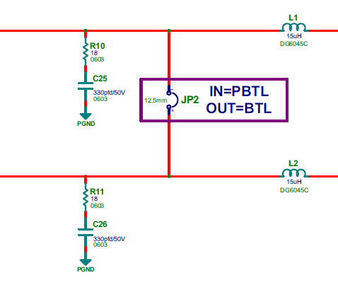
I have a question regarding the TAS5731M amplifier.
When I do not have the amplifier without any charge, I can see that the coils are getting quite hot, 
a symptom that current is passing through them but I do not understand where that current flows if there is not a speaker connected.
Could you explain it to me please? Could we prevent this current from flowing around by some I2C record ?

Thanks you in advance.

Regards,

Antonio Guzman

  • Hello Antonio! I have looped in Shawn to Answer your question. What type of signal are you putting into the EVM/ Also, what type and spec of power supply are you using? Thanks, Jeff
  • Hi Antonio,
    This is not expected, the coils shouldn't be hot if the load is open. There is no large current through the coils, so the temperature on them shouldn't be very high.
    Are you using TAS5731EVM? if not, please show me your SCH. If yes, did you rework on the EVM? What is the power supply used here?
    Please refer to TAS5731EVM user's guide in this link www.ti.com/.../slou331a.pdf
    Best regards,
    Shawn Zheng
  • Hi,

    I am using TAS5731EVM (BTL configuration, JP1 IN, JP2 and JP3 OUT) and a power supply of 24V DC.

    When the load is open and I don't put any signal in input (SDIN), the coils are very hot (50ºC approx).

    I have the next signal in output (Signal measured between a terminal of the BTL OUTAB connector and PGND).

    I think this signla is PWM carrier but I need to remove this signal in output, It is possible?

    Thank you.

    Antonio Guzman

  • Hi Antonio,
    Did you close JP2 and JP3 on TAS5731EVM? When you use BTL mode, please leave them open. About the usage of TAS5731 EVM, I think you could take a look at the user's guide http://www.ti.com/lit/ug/slou331a/slou331a.pdf It would be very helpful. 

    From your scope captured screen, looks like it's the ripple on the output according to the frequency. How much is the amplitude?

    This frequency is out of audio frequency band, so you don't need to tackle it actually. If you need smaller ripple, you could use larger inductors in the output filters.

    Best regards,

    Shawn Zheng

  • Thank you for your response.

    1) Did you close JP2 and JP3 on TAS5731EVM? --> No I did. I leave them open as user's guide explain it (JP2 and JP3 open. JP1 close).

    2) The amplitude is 1V peak-peak so we have 2W (BTL have 2 speakers) aprox. in the output although there is no streaming. It's a big problem due to temperature.

    3) Effectively this frequency is out of the band of audio but IF I need to tackle it to have no problems in the tests of EMC (emission).

    My question is this: Could not we completely tackle this signal by some I2C record for example?

    Thnk you again.

    Regards,

    Antonio Guzman
  • Hi Antonio,
    Thanks for your feedback. Your jumper configuration looks no problem. I think the ripple current through inductors could cause some power consumption but couldn't cause too high temperature when load is open. Because in this case, the ripple current is not high and inductor DCR is also very low, then the power consumption on inductors should be very low.
    You could try to use BD mode instead of AD mode to see if there is any improvement. EMI is a system issue, here is some system method to minimize this issue. PWM switching is the main EMI source, but when it go through LC filter, the interference degrades a lot. That is why subbers are used on the output to bypass the high frequency components.
    You can also use larger inductors to supress the interference further. When designing PCB layout, put the LC filters close to the output of the device as much as possible to short the trace where PWM signal runs.
    In addition, there are some ways to suppress the ripple current on the output, though I don't think the ripple could cause EMI issue. For some other devices which has adjustable PWM switching frequency, a smaller ripple can be achieved by using a higher PWM switching frequency. But this feature is not available on TAS5731. Lower PVDD level or larger inductors will cause lower ripple on the output.
    Please refer to this material about LC filter www.ti.com/.../slaa701a.pdf
    Best regards,
    Shawn Zheng