This thread has been locked.

If you have a related question, please click the "Ask a related question" button in the top right corner. The newly created question will be automatically linked to this question.

TAS5731M: Output muted when volume is too high

Part Number: TAS5731M
Other Parts Discussed in Thread: TAS5731

Hello,

Actually I am working with TAS5731M in BTL mode, and when the sound is too high the outputs are deactivated (muted).

I implemented this on a board and it worked well, but now on the new design I have this problem.

I took the same schematic (same as EVM board) and routing file for the two designs, the only thing that's changed is the thickness of the PCB (1mm to 0.8mm now). 

I am reading some register before and after the TAS is muted  : 

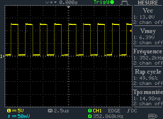
  • Error Status Register : Before muting, the bit clip indicator appears (0x04). 
  • System control Register : When the TAS is muted the value in this register change from 0x00 to 0x40. It means the outputs are hard muted but I don't know why the TAS is doing that

To restart the TAS I have to power it down and restart it. 

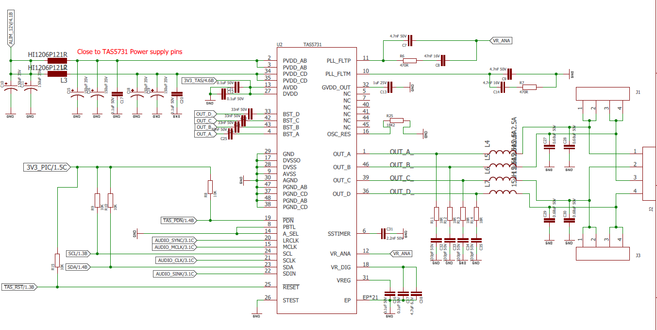
Please find below the schematic used. 

Thanks for your help

Mallyck

  • Hello! Shawn can help you with further questions, but it looks like you are driving the system with a PVDD of 12V, but it is not clear what type of load you are driving. Can you give us more info on the load? It is highly likely that you are driving too much current through the device and it is just tripping the system. Please reference section 7 parameters and in particular the output power vs. input power according to the type of load. This should help you. Thanks, Jeff
  • Thanks for your quick reply !

    Yes PVDD is 12V and the load is 8 ohm speaker

    What do you mean by "tripping the system", is there a security mode for that overcurrent? And if it's that problem is it normal that in Error Status Register This type of error is not detected ?

    Regards
  • Hi Mallyck,
    Thanks for your reply. I reviewed the SCH and didn't find obvious issue. Form the info you sent, I believe this issue is OT Fault.
    If device junction temperature exceeds around 150 degreeC, the device is put into thermal shutdown, and all outputs are set into Hi-Z state. The copper thickness on the board is actually strongly related to the PCB thermal performance, so this revision of board has worse thermal performance and gets into Hi-Z mode more easily with output power because of the thinner cooper thickness.
    About the thermal design, TI has a lot of materials, please refer to www.ti.com/.../slma002g.pdf www.ti.com/.../slua566.pdf
    Best regards,
    Shawn Zheng
  • Hi Shawn,

    Thanks for your quick reply. This morning we tested the system with a quite high volume during a long time and the TAS5731M didn't put the output in default. It's just when the input is too high (like a gunshot in a music). We are still reading the "Error Status Register" and the bit D1 "Overcurrent, overtemperature, or undervoltage errors" is not set to 1. 

    The copper thickness didn't change, it's just the thickness of the FR4 core.  

    We are soldering the TAS5731M manually with a soldering rework station at a really high temperature (around 400°C),could it affect the function of the system ? 

    Best regards

  • Hi Mallyck,
    Thanks for the info. So when the input is large -> volumn is small -> the output is also small, the issue will occur. But when the input is small -> volumn is large -> the output is also large, the issue never occurs. Is my understanding right? What if use very large input signal but open the load/speaker? Does the issue still occur in this case?
    It's possible to damage the device by exposing it under high temperature for a long time. Could you please try with another new device? Or is it possibly a solding issue?
    Best regards,
    Shawn Zheng
  • Hi Shawn,

    So to be clear, the test is :
    Input is 200 Hz sine at maximum level. Then I move the value in volume register (register 0x07). On my old revision the TAS5731M is working well from 255 to 0. But with the new board, the same input and when I achieve 70 the system is tripping. I have tried with other frequencies but the result is the same, the issue appear when I turn up the volume.
    I tried by opening the load the issue doesn't appear.
    I have 5 prototypes and it's the same on all of them.
    Best regards
  • Hi Mallyck,
    Thanks for your explanation. So the only hardware difference between the two revisions is the PCB thickness, right? Is there any difference in software? Could you plesae send me your register setup for the normal case and after the issue occurs? If possible, please also send me the scope screen capture for the output when the issue is triggered.
    Could you please try to set 0x7 in the Modulation Limit Register(0x10) to lower the PWM duty cycle limit to see if there is any improvement?
    And aslo could you please confirm that 33nF capacitors are used for bootstrap capacitors on the board? If yes, please try to use larger boostrap capacitors and see if the issue still occurs.
    Best regards,
    Shawn Zheng
  • Hi Shawn, 

    For the hardware we also changed the power supply line for AVDD and DVDD. We put one LDO form 5V to 3.3V specifically for the TAS5731M that can deliver up to 300mA (ref AP7331). The 12V comes from the same source as the old board. To be sure that the problem is not from this 3.3V we took it from external power supply and the issue still occurred. 

    For the register please find below our initial configurations : 

    NAME (ADDRESS) = VALUE

    TAS5731_OSCTRIMM_REG (0x1B)   = 0x00

    TAS5731_SYSCTRL2_REG (0x05) = 0x00

    TAS5731_SDI_REG (0x04) = 0x03

    TAS5731_CH1VOLUME_REG (0x08) = 0x00

    TAS5731_CH2VOLUME_REG (0x09) = 0x00

    TAS5731_CH3VOLUME_REG (0x0A) = 0x00

    TAS5731_MODLIMIT_REG (0x10) = 0x07

    So during the tests I have seen that there is 2 problems. The first one is the one described before, when the input is too high the output are hardmuted.

    In the registers I can read 0x04 in "Error Status Register (0x02)" just before muting and then after the issue in " System Control Register 2 (0x05)" = 0x40.

    The screen capture of the output is not necessary there is 0V on all the output. This first problem happened with a gunshot fire.

    The second problem is a little bit different, with a continuous sine at 200 Hz when I turn up the volume at a certain point one speaker is muting but in the register there is no change. And the screen of the output is below : 

    output with no sound : 

    The PWM is not working on this output but on the other one it's working well. So at this point I have sound on one output but there is another problem, I can't change the volume. I can write and read the  "Master Volume Register (0x07)" the value inside is changing but nothing changed on the speaker.

    I tried to change the bootstrap capacitor to 100nF but the issue still occur. 

    Best regards

  • Hi Mallyck,
    Thank you very much for the measurement and explanation.
    This issue is really strange. I think your register setting looks no problem, so I guess it maybe a hardware issue instead of software issue. I reviewed the SCH again and found that C14=4.7nF. It should be 47nF. Could you please replace it with 47nF capacitor? Please let me know if the issue can be fixed in this way.
    Best regards,
    Shawn Zheng
  • Sorry I forgot to tell you this, but I have already seen this mistake and changed C14. It does not resolve the issue.
    Is there any security inside the TAS and not mentioned in the datasheet that can disable one output and not the other one? And do you know why the connection between the volume register and the gain of the amp doesn't work at this time ?
    Best regards
  • Hi Mallyck,
    Sorry for the late reply, beasuse I was on a bussiness trip in the past several days.
    I think this issue is caused the too large output signal. In this case, the output is clipped and then device gets into protect mode when enlarging the input signal amplitude too much. Why don't you enable DRC on TAS5731 to protect the device or speaker. In section 9.3.11 in TAS5731 datasheet, you can find the introduction of DRC blocks. We also have a very detailed document about DRC usage www.ti.com/.../sloa148.pdf.
    DRC provides compression capabilities by setting the appropriate parameters configuration. In this case, I think you could try to use a higher compression ratio and lower threshold in DRC to make sure there is no clipping on the output.
    Best regards,
    Shawn Zheng
  • Hi Shawn 

    I already enable the DRC and reduce a little bit the value in volume register to use our board. So currently the TAS5731 is working but the volume is lower and it's a problem for our customer.

    We are thinking to make new PCB with modifying the thickness (from 0.8 to 1mm) and expand the size of the power supply line. Is it a good idea or will we have the same problem ? 

    Thanks 

    Best regards 

    Mallyck

  • Hi Mallyck,
    DRC is usually enabled to protect the speaker. I think there is no problem in your SCH. Please pay highly attention to the thermal performance when design the PCB.
    Best regards,
    Shawn Zheng
  • Hello Mallyck! Did this answer your question and can we close this message thread? Thanks, Jeff
  • Hello, 

    I finally received my new board with new design and it's working well ! It seems the problem come from the thickness of the PCB. The schematic used and route are the same as last design. 

    Thank you for your help

  • Hi Mallyck,
    Congratulations! I'm very gald that your new board is working perfectly!
    Best regards,
    Shawn Zheng