


Hello,
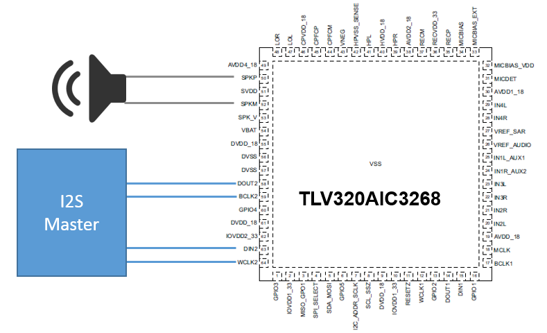
I was hoping I could get some advice on how to configure the TLV320AIC3268 to receive over I2S to the Class D SPKM and SPKP. My specifications are below and register values are attached but I can't seem to get it working. I was hoping someone could confirm I have my register values set correctly.
I2S Specifications:
- Using ASI#2 , BCLK2, WCLK2, DIN2, DOUT2
- BCLK2 to be used as the DAC_CLKIN
- TLV320AIC3268 is the I2S Slave
- Left justified
- MSB of SD data occurs in the second SCLK period
- When WS is high, SD data is right channel
- 17-bit data is rounded down to 16-data.
- Sample Frequency 44.1kHz
- 32 bit
Script to set registers:
#########################################################################################
# Audio Serial Interface #2 to Class-D Speaker
# LOL and LOR are mixed 0dB/0dB to convert stereo to mono
# AVDDx_18, HVDD_18, CPVDD_18 = 1.8V; IOVDDx_33, RECVDD_33 = 3.3V
# SVDD, MICBIAS_VDD (JP37 1-2 + JP44 2-3), SPK_V = 5V, DVdd_18 = 1.8V
# No Master Clock, BLKC2 to be used as CLKIN
# MCLK = NA, BCLK2 = DAC_CLKIN = 1.4112MHz, Fs = 44.1kHz
# PLL Disabled, DOSR = 32,
# Audio Serial Interface #2 signals routed to DIN2 (DIN), BCLK2 (BCLK), DOUT2 (DOUT),
# WCLK2 (WCLK) - Codec ASI#2 is Slave
#########################################################################################

#########################################################################################
# Codec Software Reset
#########################################################################################
w 30 00 00 # Initialize to Page 0
w 30 7f 00 # Initialize to Book 0
w 30 01 01 # Initialize the device through software reset
d 1        # Delay 1 millisecond

#########################################################################################
# FIFO Configuration
#########################################################################################
w 30 00 00 # Select Page 0
w 30 7f 78 # Select Book 120
w 30 32 80 # Enable DAC FIFO
w 30 7f 64 # Select Book 100
w 30 32 80 # Enable ADC FIFO
w 30 7f 00 # Select Book 0

#########################################################################################
# Power and Analog Configuration
#########################################################################################
w 30 00 04 # Select Page 4
w 30 77 c0 # Disable miniDSP power-up sync with ASI
w 30 00 00 # Select Page 0
w 30 0d 00 10 # Program DOSR = 16 -AB
w 30 14 10 # Program AOSR = 16 -AB
w 30 00 01 # Select Page 1
w 30 01 00 # Disable weak AVDD to DVDD connection, make analog supplies available

#########################################################################################
# For BiQuad Configuration see Script '0.1.txt'
#########################################################################################

b "Device Initialized and in Standby"

#########################################################################################
# Clock configuration
# MCLK = NA, WCLK = 44.1 kHz (slave)
# BCLK = 44.1kHz * 32bit * 1 channel = 1.4112 MHz
#########################################################################################
w 30 00 00 # Select Page 0
w 30 04 40 # Set DAC_CLKIN as BCLK -AB
w 30 0b 81 # NDAC = 1
w 30 0c 82 # MDAC = 2
#BCLK = 44.1kHz * 32bit * 1 channel = 1.4112 MHz
w 30 0d 00 # Program the OSR of DAC to 16 to get
w 30 0e 10 # DAC_FS = DAC_MOD_CLK / DOSR = 1.4112MHz / 32 = 44.1kHz  -AB

#########################################################################################
# Audio Serial Interface Routing Configuration - Audio Serial Interface #2
# ASI #2 connected to BCLK2, WCLK2, DIN2, and DOUT2 pins
#########################################################################################
w 30 00 04 # Select Page 4
w 30 11 18 # Audio Serial Interface #2 = I2S mode, 32-bit -AB
w 30 1a 00 # For Audio Serial Interface #1,
           # Select BCLK2 as BCLK input and WCLK2 as WCLK input
w 30 17 01 # Route ADC data to Audio Serial Interface #2
w 30 18 50 # ASI#2 Left Channel data sent to Left Channel DAC,
           # ASI#2 Right channel data sent to Right Channel DAC
w 30 45 04 # Select WCLK2 pin as WCLK for Audio Serial Interface #2
w 30 46 04 # Select BCLK2 pin as BCLK for Audio Serial Interface #2
w 30 47 22 # Select DOUT2 pin as DOUT for Audio Serial Interface #2
w 30 48 20 # Select DIN2 pin as DIN for Audio Serial Interface #2
w 30 76 16 # Only ASI#2 Routed to DAC miniDSP Data Input 1

#########################################################################################
# Signal Processing Settings
#########################################################################################
w 30 00 00 # Select Page 0
w 30 3c 01 # Set the DAC Mode to PRB_P1

#########################################################################################
# Output Channel Configuration
#########################################################################################
w 30 00 01 # Select Page 1
w 30 03 00 # Set PTM mode for Left DAC to PTM_P3 (default, writing here optional)
w 30 04 00 # Set PTM mode for Right DAC to PTM_P3 (default, writing here optional)
w 30 16 c3 # Enable DAC to LOL/R routing and power-up LOL/R
w 30 2E 00 # Route LOL to SPK @ 0dB -AB
w 30 2F 00 # Route LOR to SPK_RIGHT_CH_IN @ 0dB -AB
w 30 30 11 # Set SPK Gain @ 6dB, unmute SPK_RIGHT_CH_IN
w 30 2D 06 # Power-up SPK, route SPK_RIGHT_CH_IN to SPK
w 30 00 00 # Select Page 0
w 30 3f c0 # Power up the Left and Right DAC Channels
w 30 40 00 # Unmute the DAC digital volume control
d 40       # Wait for reference to power up


b "Device in Operational Mode"

#########################################################################################
# For Power Down Sequence see Script '0.2.txt'
#########################################################################################
I2C log setting registers:
# -----------------------------
# LOG START  Thu Jul 27 14:54:59 2017

# -----------------------------
# LOG START  Thu Jul 27 15:12:02 2017

w 30 00 00
w 30 7f 00
w 30 01 01
w 30 00 00
w 30 7f 78
w 30 32 80
w 30 7f 64
w 30 32 80
w 30 7f 00
w 30 00 04
w 30 77 c0
w 30 00 00
w 30 0d 00 20
w 30 14 20
w 30 00 01
w 30 01 00
w 30 00 00
w 30 04 40
w 30 0b 81
w 30 0c 82
w 30 0d 00
w 30 0e 20
w 30 00 04
w 30 11 18
w 30 1a 00
w 30 17 01
w 30 18 50
w 30 45 04
w 30 46 04
w 30 47 22
w 30 48 20
w 30 76 16
w 30 00 00
w 30 3c 01
w 30 00 01
w 30 03 00
w 30 04 00
w 30 16 c3
w 30 2e 00
w 30 2f 00
w 30 30 11
w 30 2d 06
w 30 00 00
w 30 3f c0
w 30 40 00
w 30 00 00
w 30 7f 00
w 30 01 01
w 30 00 00
w 30 7f 78
w 30 32 80
w 30 7f 64
w 30 32 80
w 30 7f 00
w 30 00 04
w 30 77 c0
w 30 00 00
w 30 0d 00 10
w 30 14 10
w 30 00 01
w 30 01 00
w 30 00 00
w 30 04 40
w 30 0b 81
w 30 0c 82
w 30 0d 00
w 30 0e 10
w 30 00 04
w 30 11 18
w 30 1a 00
w 30 17 01
w 30 18 50
w 30 45 04
w 30 46 04
w 30 47 22
w 30 48 20
w 30 76 16
w 30 00 00
w 30 3c 01
w 30 00 01
w 30 03 00
w 30 04 00
w 30 16 c3
w 30 2e 00
w 30 2f 00
w 30 30 11
w 30 2d 06
w 30 00 00
w 30 3f c0
w 30 40 00

