This thread has been locked.

If you have a related question, please click the "Ask a related question" button in the top right corner. The newly created question will be automatically linked to this question.

DRV135: Resistors on the Outputs as shown in application notes

Part Number: DRV135

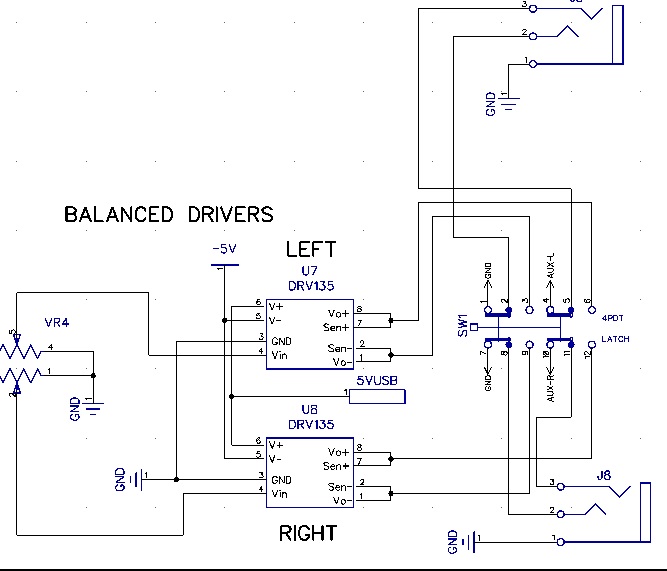
I am using 2 DRV135 in a digital audio mixer project. The power derived from USB is +/-5v (close to minimum spec) I do not have resistors that are shown in the application diagram

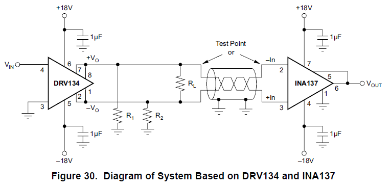
I would like to know what these resistors do and what values they need to be. I am thinking that I have a problem if those parts are omitted. can you please advise. I am looking to have an output

that would drive a typical powered speaker. 

  • Hello Paul,

    Our audio experts are out so I will get back to you again, but getting more information (such as how long these traces to your speakers are and if they are driving a receiver, audio amplifier, or speaker directly) will be helpful.

    I assume you are referring to this diagram:

    which has this performance for these combinations of resistors.


    Overall, R1, R2, and RL represent the 600Ohm resistance the DRV135 can drive it's signal through. Having these resistors increases your total harmonic distortion and noise performance. This is most likely due to the fact that the output amplfiers in in the DRV135 will be able to drive closer to its power rails. Whether you're driving your signals through a cable or not having these resistors will improve THD+N vs. Frequency.

    Peter Iliya

    Precision Amplifiers

    Tucson, Arizona

  • Yes, figure 30 is my reference for the question about the resistors. The output jacks are close to the DRV135 chips, but pass through a bypass switch first. The output is expected to go through a 15' cable (2 wires plus shield) to the input of an amplified speaker 10k input impedance typical. Figure 1 (i guess) would be more like the 15' cable compared to figure 2 500' cable. C looks like the best performance. With R1,R2 the symbol is infinity? would that be no resistor?
  • Hey Paul,

    Yes, R1 and R2 at infinity means the resistors would not be there. I'm not sure if driving the signal through a 15' cable is closer to "No Cable" vs. a 500' cable. I will get back to you on this.

    Peter Iliya
    Precision Amplifiers Applications
    Tucson, AZ
  • Hello Paul,

    I was speaking with my colleagues about the purpose of having R1, R2, RL in Figure 31 of datasheet. The 600Ohm loads indicate how well this part drives low-impedance loads in small-signal circuity. The 600Ohm value comes from older equipments standards that has now become an indicator in datahseets. Since your signal will drive into the 10 kOhm input impedance of your audio amplifier, you actually do not need these resistors (R1,R2,RL) at any point in your signal path.

    I hope this helps and reach out if you have more questions.

    Best,

    Peter Iliya
    Precision Amplifiers Applications
    Tucson, AZ