This thread has been locked.

If you have a related question, please click the "Ask a related question" button in the top right corner. The newly created question will be automatically linked to this question.

TINA/Spice/TPA6138A2: LPF and Audio amplifier not working

Part Number: TPA6138A2
Other Parts Discussed in Thread: TINA-TI, , PCM1789

Tool/software: TINA-TI or Spice Models

I am trying to use the TPA6138A2 both as LPF/diff to single and as audio amplifier. I followed the datasheet exactly for 2nd order LPF and amplifier but the output sound is noisy. Then after days of not able to make it work, i tried the simulation of TPA6138A2 as provided by the TI. Herein, the model does not simulate giving me error saying:

Current of component: U2.XU5.XR108.VSENSE

Node: 132
Component/Terminals: .U1 XU5.45

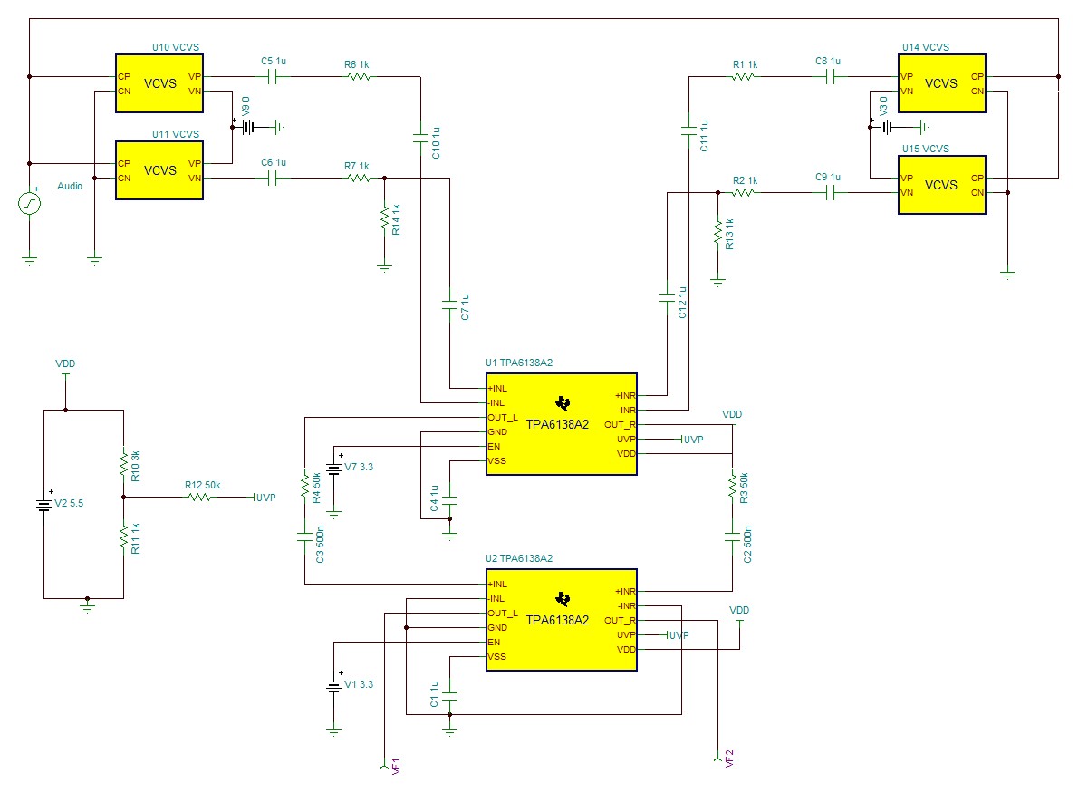
My circuit is attached herewith. I have a 0.5uF capacitor before the LPF as indicated by the datasheet. Also I have 1uF at the input of the amplifier. Attached is also the schematic.

Is there any problem with the TPA6138? I don't see me doing anything wrong with the circuit.

PCM1789TPAconnection.PDF

  • i have not connected the UVP, is it mandatory?
  • Hi Ravi,

    One of my colleagues will be responding soon with further information.

    Best Regards
    José Luis Figueroa
    Applications Engineer
  • Hi Ravi,

    It is not mandatory to connect UVP.
    There are some things that should be improved in the TINA simulation, like the feedback net so the device gain is set properly. This is for both U1 and U2. You should also add a load at the outputs of U2.

    How is the output sound noisy? Do you have any capture of the output signal?
    Charge pump capacitors and decoupling capacitors are close to the device? Are these capacitors placed on the same layer as the TPA6138A2 units? (No vias)

    Best regards,
    -Ivan Salazar
    Audio Applications Engineer - Low Power Audio & Actuators
  • hi,

    I think that the pump capacitor and decoupling capacitor are close. But then again, the sound is noisy and when I increase the volume on the PC the noise increases and buries the actual audio. So could this be due to pump capacitor and decoupling capacitor?

    attached herewith is the schematic. I have used 1uF at the input of LPF/differential to single circuit and at the input of the amplifier I have 100kohm for volume reduction(because volume is very high), and a 0.5uF according to the 1/2pifR formula in the datasheet for 20Hz low audio.

    Would you please further comment.

    thank you6180.PCM1789TPAconnection.PDF

  • adding, is LPF and the amplifier different application or is the LPF build into the amplifier?
  • Ravi,

    Your schematic looks good, it is pretty much similar to the EVM.
    Why is it you're using two stages of TPA6138A2 if volume is too high?
    Is there a chance that you are able to capture or hear the audio on different places? Lets say between the input of U3 and the output of U2? And also between the input of U2 and the output of U1? I would like to identify if noise is coming from a previous stage.

    Regarding the LPF, your current circuit from the schematic you've shared is already an LPF in multi-feedback topology. TPA6138A2 can be used as an opamp, so if you add feedback and input capacitors the amplifier can be used as a MFB filter. There are some details on data sheet section 9.4.2. The gain can be obtained from: Gain = R2/R1 and cutoff frequency from: fc = 1/(2*pi*sqrt(R2*R3*C1*C2)).
    I used figure 8 from data sheet to make reference on resistors/capacitors numbers on the formulas.

    Best regards,
    -Ivan Salazar
    Audio Applications Engineer - Low Power Audio & Actuators
  • So, TPA6138 can act as both LPF and amplifier simultaneously? no need for separate LPF?

    Also the output of PCM1789 is 4Vpp centered at 2.5V while the input to the TPA6138 is 0V to 3.3V, so do i need to attenuate input signal to TPA6138? my attached schematic does not have this?