This thread has been locked.

If you have a related question, please click the "Ask a related question" button in the top right corner. The newly created question will be automatically linked to this question.

PGA2311: Default with mute fonction

Part Number: PGA2311

Hi

I use a PGA2311 with a atmega2560 (clock 16Mhz)

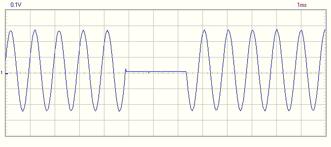
The mute fonction is achieved by hardware control. I have some trouble with this, when mute is enabled, the output signal is =0 for only a few cycle.

You can see on a screen shot the output when mute is enable (1khz input signal).

Any idea ?

Regards

  • Hi

    Do you think it is a problem with my firmware (made by an arduino mega2560) or a hardware problem?

    Thanks

  • Hi Georges,
    I would guess that this is a firmware problem, although it's possible there's something going on in hardware that could cause it. Could you also attach an oscilloscope plot of the input to the Mute pin? If Mute is consistently pulled low during the entire plot above, then there's something else causing the issue, but if Mute goes low, but returns high after ~2ms, that would explain the signal above.
  • Hi Alex

    Thanks for you answer!

    I thought that it was a problem with the mute pin and I had tested it, and the signal is OK (always pulled low during the test). I haven't got a screen shot but I can made a new test to be sure.

    Regards

  • Hi Georges,

    I had a thought. Is it possible that there's a bad solder joint on the mute pin connection? I'm wondering if it's possible that there is a capacitive coupling (but no DC path) between the microcontroller and the PGA. In that case, pulling Mute low would initially mute the amplifier, but leakage currents would start charging that parasitic capacitor, causing its voltage to rise and eventually exit the mute state. This may not show up with a DMM or oscilloscope reading, as the DMM or oscilloscope probe would add enough load resistance to the pin to pull it fully low. Of course, a side effect of this would be that any time the Mute pin was probed, the PGA should mute. If that's not the case, then it's possible that the PGA is simply damaged. In that case, you might try swapping to a new PGA to see if the problem persists.
  • Hi Alex

    Thanks for your answer.

    I have changed the PGA with a new one, and nothing change. It is possible that it is a problem with a solder, i'm going to verify this, and I come back.

    regards

  • Hi

    I have verified all solders and connections, nothing change. But, when I verify the mute pin with oscilloscope while verify the output, the mute fonction is OK !

    I think it is a hardware problem, like Alex describe. The problem is that the microcontroller is not near the PGA chip. Do you think a 1MR (for example) résistance between the mute pin and ground can solve my problem?

    Regards

  • Hi Georges,

    I wouldn't expect a pulldown to be necessary on the output of the microcontroller. Typically logic outputs should be fairly low impedance. Could you verify that there's continuity (near 0 ohms resistance) between the microcontroller pin and the PGA2311 mute pin? I'm wondering if it's possible there's a small fracture in the trace carrying the mute signal.
  • Hi Alex

    The resistance between the µC pin and the mute pin is 0,3 R, tested with a multimeter.

    Don't you think it is possible there is a coupled capacitance with other layer, because the µC is about 40 cm distant to the PGA ?

    Regards

  • Hi Georges,
    It's possible there's capacitance on the line, but I wouldn't expect that to produce this symptom. This looks more like a series capacitance in the connection between the microcontroller and the PGA. As one last test, does the same issue happen with more than one microcontroller? I wonder if it's possible that there's a problem with that I/O pin on the microcontroller.
  • Hi Alex

    I'm just finalised the prototype of an audio amplifier. I will make a next prototype in a couple of week, with some differences on the PCB. I'll come back with feedback.

    Thanks for your implication about my problem

  • Hello

    I made a new prototype: new PCB, less connections but same schematic. The problem is not solved. I put a 220k resistor between the mute pin and ground, near the pga. This don't fixed my problem.

    I use the MOSI pin for drive the mute pin, wich is use for flashed the bootlaoder. Also, the µP  (an atmega 2560), is use for many applications (oled display, IR receiver, temperature analysis, fan control (pwm) several push buttons and other fonctionality. Perhaps it is a problem with the firmware...

    regards

  • Hi Georges,
    Would it be possible to take a look at your schematic? It's possible that there's an issue with the firmware, but I'm not familiar enough with the Atmega to be certain. If you can't share the schematic publicly, you can send a pdf or other image to a.davis@ti.com instead.
  • Hi Alex

    I send you an email

    Regards

    Georges