This thread has been locked.

If you have a related question, please click the "Ask a related question" button in the top right corner. The newly created question will be automatically linked to this question.

TLV320AIC3104-Q1: ADC not working, register programming sequence

Part Number: TLV320AIC3104-Q1
Other Parts Discussed in Thread: TLV320AIC3104

Hello TI,

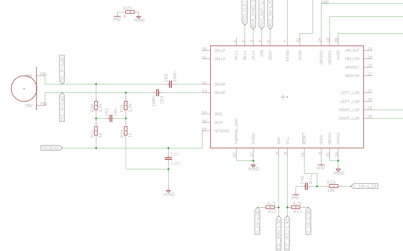
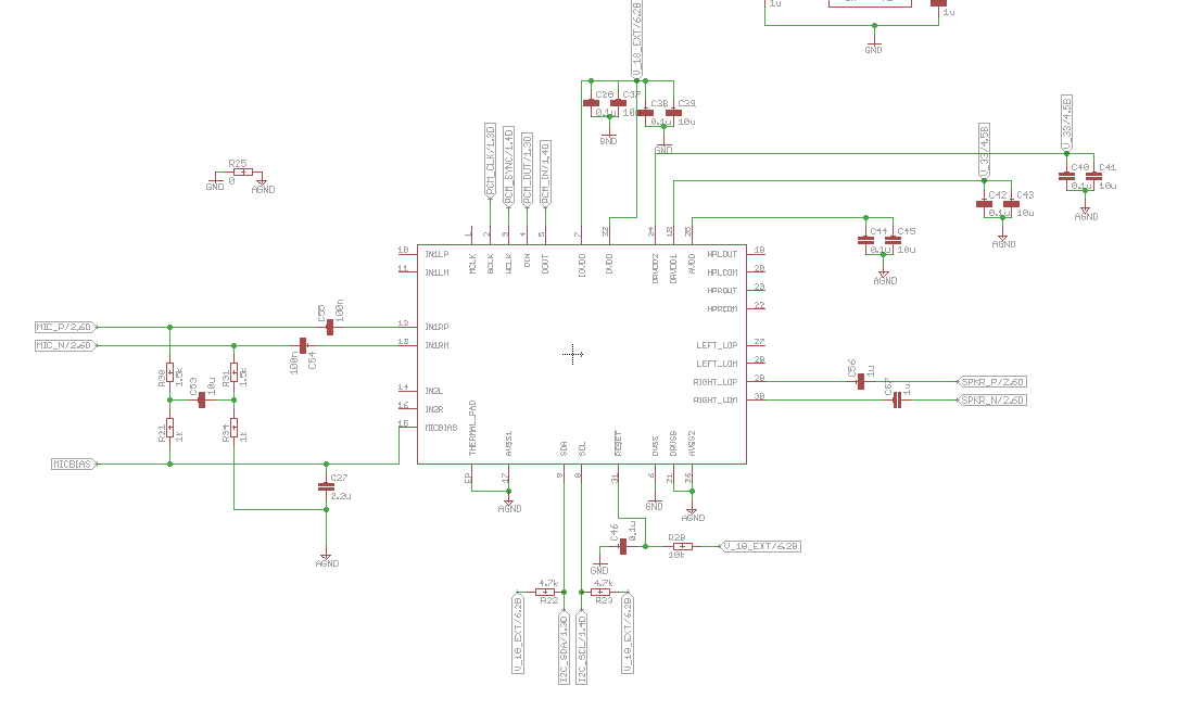
Please find below the schematics for the audio codec as recommended by Quectel. We are using the codec for eCall with a Quectel EC21 Modem. 

The output seems to be working fine. However the microphone is a problem. 

The MICP and MICN are directly connected to a electret capsule mic. 

The register programming sequence is as below. I tried working only with the right ADC in the beginning however since it wasn't working, I'm used both the ADCs. 

Could you please check the register configuration and let me know what I'm missing? 

The microphone seems to be working since I notice changes in the analog singal on MICP when it detects sound. 

0x18,0x01,1,0x80 {sw rest}
0x18,0x66,1,0x82 {clk}
0x18,0x65,1,0x01 {clk}
0x18,0x19,1,0x80 {mic bias to 2.5V register}
0x18,0x15,1,0x80 {write to register 21 value 1000 0000.. gain set to 0db and  diff mode}
0x18,0x16,1,0x84 {write to register 22 value 1000 0000.. gain set to 0db right ADC channel power up and diff mode}
0x18,0x13,1,0x7C {register 19 power up left ADC}
0x18,0x0F,1,0x0F {Unmute left PGA, set gain to 3dB register 15}
0x18,0x10,1,0x0F {Unmute Right PGA, set gain to around 3dB register 16}
0x18,0x07,1,0x1E {000 00 11 11 0 Codec Data-Path Setup Register, right DAC and left DAC play mono mix of right and left DAC}
0x18,0x29,1,0x50 {register 41 Right and left DAC route to L3 and R3}
0x18,0x25,1,0xC0 {register 37, power up right DAC}
0x18,0x2B,1,0x00  {register 43, unmute}
0x18,0x2C,1,0x00 {register 44, unmute}
0x18,0x5D,1,0x09 {register 93 RIGHT LOP/M output level control register unmute and power up}
  • Hi, Preadeep,

    Sorry for the delay, my colleagues will take a look to your question and will provide a response by tomorrow.

    Best Regards,

      -Diego Meléndez López
       Audio Applications Engineer

  • Hello Diego,

    thank you for your reply. It would be much appreciated if your colleagues could get back to me soon.

    Are there any restrictions as to what kind of mic I should be using with this circuit? Any suggestions would be appreciated.

    I can see changes on the MIC_P line, in the order of milliVolts when the microphone is subjected to sound. However this change is not being translated in to digital output from the codec.

    Thanks again!

  • Hello Pradeep,

    Sorry for the delayed reply. I took a look at your register settings, and I noticed that you are not writing to register 0x11 or 0x12. These registers contain the control bits for the Left and right ADC PGA mutes. The default is mute.

    best regards,
    -Steve
  • Hello Steve,

    thank you for the reply. Register 0x11 (Register 17) and Register 0x12 (Register 18) are for the MIC2L/2R inputs, which I'm not using. I'm using only the MIC1RP and MIC2RM inputs as per the hardware schematic. The Register 0x11 and 0x12 should have no effect I believe. Please correct me if I'm wrong.
  • Pradeep,

    I must be going cross eyed going back and forth from hex to decimal. You are quite right, register 17 and 18 are for MIC2L/R inputs.

    on our EVM I can get digital output using an electret microphone using the following settings, these are almost identical to yours, but I'm using the MIC2R/MIC2L inputs in SEmode. the EVM is connected to my computer and I can record audio on the microphone in Audacity. Can you tell me more about your test setup?

    w30 01 08
    #software reset
    w 30 11 0F
    #similar to your register 0x15 setting. (left -ADC control reg)
    w 30 12 F0
    #similar to your register 0x16 setting. (right -ADC control reg)
    w 30 15 00
    #similar to your setting on same register only I'm using SE mode
    w 30 16 04
    #Similar to your setting on same register, only I'm using SE mode
    w 30 13 7C
    #identical to your setting on same register
    w 30 0F 00
    #Similar to your setting on same register, but my PGA is 0dB (left PGA)
    w 30 10 00
    #Similar to your setting on same register but my PGA is 0dB (right PGA)
    w 30 19 80
    #mic bias

    best regards, 

    -Steve Wilson

  • Hey Steve,

    tell me about this hex decimal conversion thing! Too many browser tabs open and too many text editors open trying to convert between these two number systems and note down what on earth I'm actually trying to get done! Not to forget setting the value of the registers, again binary to hex :D

    Soo..the previous prototype I designed, I also used the MIC2R/MIC2L inputs and they worked beautifully.

    Quectel recommended we switch to the MIC1RP/RM pins since that they had a preset available for the Quectel EC21 which controls the codec, so I didn't have to set all the registers manually. It isn't working as expected.

    The schematic is as below. 

    Considering how simple the microphone is, I think all the checkboxes have been ticked. It has a bias voltage, it has the positive and the negative connected. That should be the end of it right?

    Test setup Info:

    The PCB uses a Quectel EC21 GSM/LTE modem. The modem communicates with the TLV320 using I2C. The modem provides the clock for the audio codec. 

    PCM_CLK going to BCLK = 2048 kHz

    PCM_SYNC going to WCLK = 8 kHz

    When I make a call from the Quectel Modem, I can hear the other persons voice, but the other person cannot hear mine. 

    I've tried the preset provided by Quectel, it does not work. So I tried settings register values manually, still no difference. 

    1. Do you have the time to test the differential inputs instead of the 2R/2L pins? That would be very helpful.

    2. In the functional block diagram, the only difference I see is that the MIC2L/2R are connected to single ended op amps and the differential as expected differential. Is this all that makes the difference?

    3. Are there any specific electret capsule microphones that work with the TLV320AIC3104?

    4. Quectel recommends 10pF and 33pF capacitors at the microphone end connected to GND to prevent GSM interference. I do not have these. Is that enough to completely destroy the input from  the mic to the codec?

    Thanks again for your time!

  • Pradeep,

    Yeah, the hex to decimal is a little obnoxious, in the devices released after this one, the decimal and hex values are given in register maps, which helps.

    regarding your questions:

    1. That was my intention actually. However someone snagged my last electret mic. I can still test this, I'll just have to pull one off another board.
    2. Correct. Thats really the only difference.
    3. as long as the mic can accept the bias voltage provided by the device, there really shouldn't be an issue. our EVM uses the CUI CMA-4544PF-W, But our customers have used this device with many different electret mics.
    4. Our EVM doesn't have those caps, it works fine. as you mentioned Quectel is just wanting to filter out any potential GSM interference. It wouldn't destroy the mic.

    Just to help troubleshoot, can you use register 91 (0x5B) to route PGA_R to RIGHT_LOP/m? w 30 5B 80
    This bypasses the ADC/DAC and just routes the output of the Right PGA strait to the output summing stage. This might show us if the mic is working or not.

    best regards,
    -Steve Wilson
  • Pradeep,

    Good news, I have been able to hook up an electret microphone in the same differential configuration as you, and connected it to in1R in differential mode, and I am able to route the PGA directly to headphones, and I can also get digital output.

    Here is the register configuration I used on the EVM.

    w 30 01 80
    # software reset
    w 30 07 8A
    # 44.1khz, dual mode disabled, R_DAC plays R_data, L_DAC plays L_data
    w 30 10 0F
    # RIGHT-ADC PGA not muted, gain = 7.5dB
    w 30 16 8C
    # Mic1RP configured for fully differential mode, 0dB right ADC powered on
    w 30 19 80
    # mic bias = 2.5V
    w 30 25 D0
    # Left and right DACs powered up
    w 30 26 20
    # HPRCOM configured as independent single ended output
    w 30 29 02
    # right dac selects R1 path, Right Dac Volume follows left dac volume control
    w 30 2C 00
    # Right DAC is not muted, volume = 0dB
    w 30 2F 80
    # DAC_L1 is routed to HPLOUT
    w 30 33 0D
    # HPLOUT output level = 0dB, HPLOUT is not muted, and is powered up
    w 30 40 80
    # DAC_R1 is routed to HPROUT
    w 30 41 0D
    # HPROUT output level = 0dB, HPROUT is not muted, and is powered up
    w 30 3F 80
    # route PGA_R directly to HPROUT (to hear mic through headphones at all times)


    Best regards,
    -Steve Wilson
  • Hello Steve,

    thanks again for the time and effort. 

    However I'm still unable to get this working. 

    Problems I've noticed

    1. MICBIAS register is set to 2.5V, but I still can measure only 1.25 V at the micbias pin. This isn't something that happened with the previous prototype. Could you kindly look at the schematics in the first post in this thread and suggest if the problem is with the hardware?

    2. I set the MICBIAS to connect to AVDD. Now I'm able to measure the AVDD voltage at the MICBIAS pin (3.3V). However the mic works only if I blow into it. Any other noises or sounds are not picked up by the microphone. Is this due to "saturation and clipping" of output signals from the PGA? Or is the problem something else entirely?

  • Hi Pradeep,

    Are you certain the mic isn't damaged? Electret mics are very sensitive to heat, if the device went through a reflow oven or something like that it could be damaged.

    best regards,
    -Steve Wilson
  • Pradeep,

    Another thought, is is possible that your resistors in the mic circuit are the wrong value? alternately where is that mic_bias output going to? The mic_bias can source 4ma of current at 2.5V, if for some reason it is connected elsewhere, and drawing more than that, you could certainly pull down the bias voltage.

    best regards,
    -Steve
  • Pradeep,

    based on your other forum posts, it sounds like you are going to a SE input, so I will close this thread and consider it resolved.

    Best regards, 

    -Steve Wilson