This thread has been locked.

If you have a related question, please click the "Ask a related question" button in the top right corner. The newly created question will be automatically linked to this question.

TPA3255EVM: Problem with input and output level

Part Number: TPA3255EVM
Other Parts Discussed in Thread: TPA3255

I am evaluating this board and I am having two issues:

  1. I am using the board for PBTL mode. I have verified that all jumpers are set properly. I am using a 2.5 Ohm resistive load. the user guide guide on page 2 states that the input should 4 Vrms when I try this input  using a pure sine wave at 900Hz, the output is extremely distorted and the board goes to fault after couple of minutes.   the maximum voltage I can use with  distorting the  output is 1.1Vrms or 2.8Vp-p. with this input level the output voltage is about 16Vrms into the 2.5 load witch much lower than the 600W. 
  2. the heat sing is getting very quickly even for few minutes of operations,

Please let me know what I should look for to increase the output without causing fault or distortion 

  • I am using 50V dc input for the board
  • Hi Abed,

    I apologize for the wait.  

    We noticed that in PBTL mode the TPA3255EVM can prematurely fault if R36 and R52 resistors aren't shorted (zero ohm) to ground instead of 10k ohms.  Have you replaced R36 and R52 with zero ohm resistors?  If not I would highly recommend doing so and see if the problem still persists.  

    Best Regards,

    Robert

  • Hello Robert, 

    Unfortunately, the board I had got damaged, I ordered a new one. When I receive it,  i will change the resistors and test again. Do I have to change the resistor back to 10K if I want to try other modes(BTL and SE)?

  • Hi Abed,

    No those resistors are only used in PBTL mode. I believe that we have corrected this issue on the newer boards and they are already set to 0ohm. I would still check them to make sure of course.

    Regards,

    Robert
  • Hello Robert,
    I checked the schematic, changing the resistors to 0 Ohm, that will not short them to ground. I am referring to the schematic in the TPA3255 user guide (doc SLOU441-July 2016) figure 6. should I change the resistor to 0 Ohm or i should connect J7=2 and J8-2 to ground.
  • Hello Robert,
    please disregard the previous post, I checked the jumper setting for J7 and J8 it is 2 to 3 so already pin 2 on both header i is connected to GND. I will change the resistor to o Ohm and try the board again
  • Hi Abed,

    Of course. Please get back to me if that solves the problem or if you will still require further assistance.

    Thanks,

    Robert
  • Thank you very much for the quick response. Hopefully I will get the board this week and I let you know how it goes. thank you again
  • Hello Robert
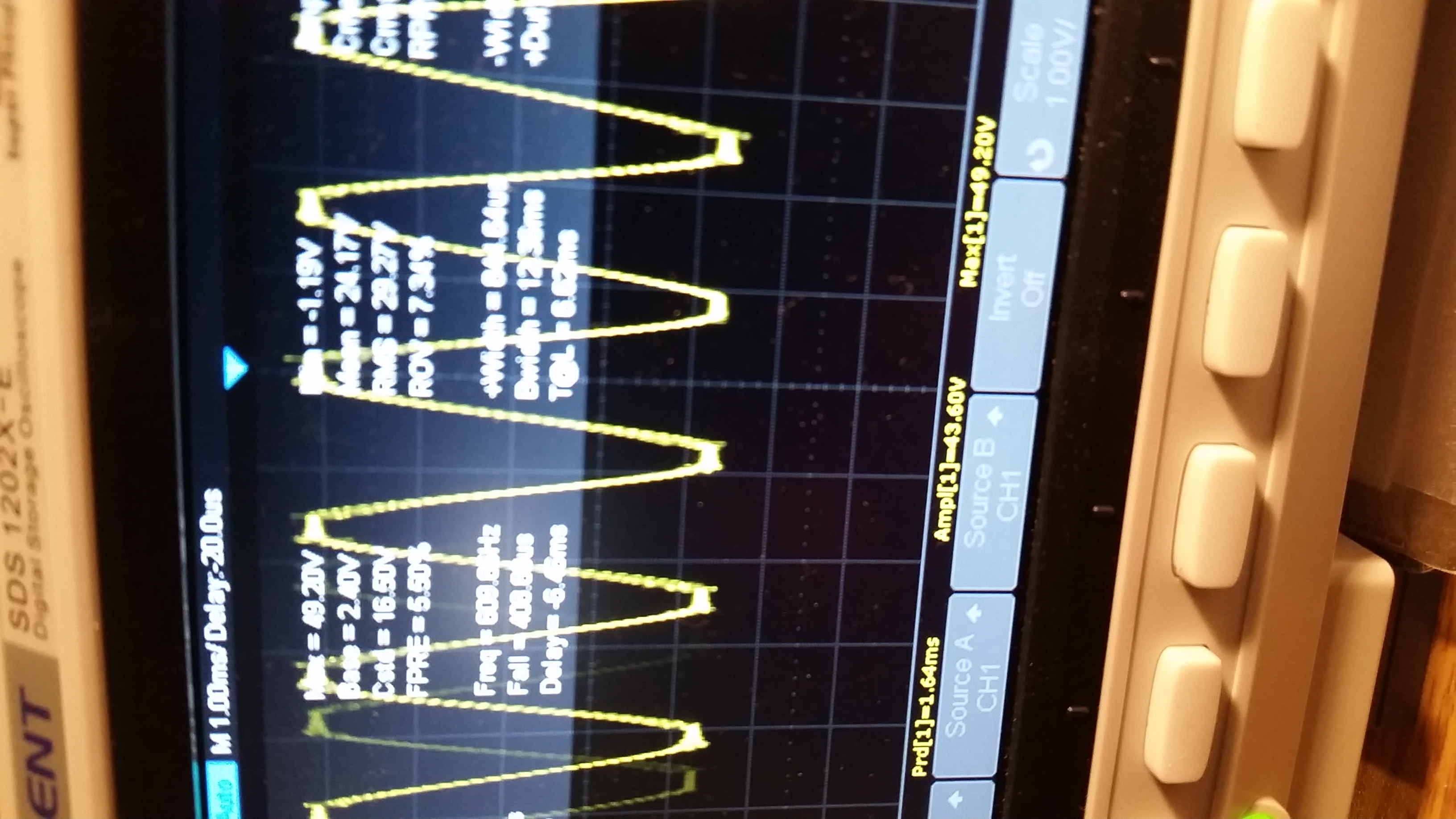
    I got a new evaluation board and I want to test it for other modes before I modified it for the PBTL mode. I am using it in BTL mode. I am using a 5Ohm resistive load (measured the value). I am using a signal generator for the input signal. The Clipping LED is going on if the output exceed 24Vrms. I was able reach 32.25 Vrms with the 4Vpp (1.4Vrms) for input signal. that is only 210W. can you please let me know why I am unable to reach 300W which should at output 38V. What do I need to do to get to that voltage without clipping
  • Hi Abed,

    I'm glad to hear you got another board in. Also thank you for sending a picture of your output.

    I will need to get a little bit more information about your system configurations:

    - What is your PVDD voltage?

    - Is your input signal differential or single ended?

    Regards,

    Robert

  • Hello Robert 
    I am using single ended input for both input A and C. 
    I started with PVDD at 51.5Vdc. I am now at 48Vds

    Abed Yassine

    Product Engineering Manager

    e: ayassine@alertus.com

    o: 202.ALERTUS (253-7887) x773

    c: 401.474.3635

    11720 Beltsville Drive  |  9th floor  |  Beltsville, MD 20705


  • Hello Robert,
    I responded to your email I am not sure if you have received my email. Anyway, the PVDD started at 51 Vdc, during test and st full load it drops to 48 Vdc
    the input signals are single ended.
    As I mentioned before, I started seeing distortion and clipping when the output exceed 24 Vrms
    the heat sink temperature is rising to 80 degree C. the board is shutting down when after 8 minutes when I push the output to 32V
  • Hello Robert, 

    I responded to your email and I posted the following message 

    the PVDD started at 51 Vdc, during test and st full load it drops to 48 Vdc 
    the input signals are single ended. 
    As I mentioned before, I started seeing distortion and clipping when the output exceed 24 Vrms
    the heat sink temperature is rising to 80 degree C. the board is shutting down when after 8 minutes when I push the output to 32V

  • Hi Abed,  

    I was able to recreate your configuration and began testing to see what exactly is happening.  When I ran the device at 1.4Vrms I noticed the device would get about 3% THD+N, which is about what I would expect in your setup.

    First and foremost, the datasheet says you will be able to get 315W stereo into 4 Ω in BTL configuration at 10% THD+N.  That's also assuming your using 51V for PVDD.  However for 1% THD+N with the 51V PVDD and 4 Ω in BTL, you can reach 260W.  

    The reason you aren't reaching 260W is due to having a larger load and lower power level, but you are getting relatively close.  For PBTL the same can be said about the 600W output is also about 10% THD+N, which as you have seen, has obvious clipping on the output.  

    If you are looking for power output levels that aren't very distorted, I would recommend looking at the 1% THD+N power levels instead of the 10% THD+N.

    Best Regards,

    Robert