This thread has been locked.

If you have a related question, please click the "Ask a related question" button in the top right corner. The newly created question will be automatically linked to this question.

OPA1641: OPA1641 Application

Part Number: OPA1641
Other Parts Discussed in Thread: OPA1642, TL971, RC4558, OPA1662, OPA1692

Hi TI,

My application is: 

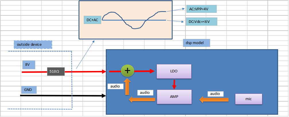
The external device only provides 8V power to the DSP module, and then the DSP module should output an audio signal with a peak to peak value of 4V and is superimposed on the 8V, and the external device is to demodulate the audio signal from the 8V.Is this usage OK?

The following diagram: 

  • Hi Hardy,

    I believe this should work, but there will be some challenges operating from an 8V supply. If your device consumes 3mA of quiescent current (1.8mA of Iq for OPA1641, plus 500uA microphone Iq, plus 700uA of overhead), the available supply drops to 6.5V. This means that the supply into the LDO would nominally be around 6.5V, but can dip closer to 4.5V (or possibly less) when the output swings to its lowest voltage. Since the OPA1641 has a minimum supply voltage of 4.5V. It's very likely that for low frequency, high amplitude outputs, you'd drop below its minimum supply, and performance would be unpredictable. You'll also need an LDO with a very low dropout voltage to accomplish this. This becomes less of a challenge if you can provide 10V or 12V power instead of 8V, as that will give you much more headroom.

    I've attached a TINA simulation of a possible circuit for this using an OPA1642 and an electret microphone. Gain may need to be tweaked depending on your selection of microphone and desired output level. I used a simple zener diode regulator for the supply, which should help reduce power supply ripple without consuming too much quiescent current. This zener and R2 could be replaced with a low-dropout, low quiescent current LDO instead, if desired. 

    Much of the microphone amplifier model in this was based off of a TI Precision Design, which can be found here: http://www.ti.com/tool/TIPD181 

    TINA-TI file

  • Hi Alex,

    Thank you for reply!

    Today, we use TI's 3 different kinds of op amp to simulate, the models are TL971, OPA1641, RC4558. From the simulation results, RC4558 is ideal, but the output is only 3.5V. Is it possible to recommend a op amplifier that meets the needs of 4V?

    The attachment is emulation circuit diagram. Thanks.Phantom-TINA-TI-tp37601-tl971.TSCPhantom-TINA-TI-tps7601-rc4558.TSCPhantom-TINA-TI-tps76301 op1641.TSC

  • Hi Hardy,
    One other issue I realized you'll have with these supply voltages on OPA1641 and possibly RC4558 is that when running from a 4.5V supply, the valid input common-mode range only extends up to V+ - 3.5V for the OPA1641 (so 1V max input common mode), and about 3V from each rail for the RC4588. Since the inputs to the amplifier will need to sit at mid supply (2.25V) for maximum output swing in the circuit I attached, neither of these options will work, as 2.25V exceeds the common mode range for either device.

    Another device to consider might be the OPA1692, although it's in preview currently and will release later this year. Another option would be the OPA1662, which is already released. Both operate down to lower supply voltages than OPA1641 or RC4588, and have better input common mode range specifications as well.

    Regarding output swing, this will be dependent on your actual audio source configuration. In the simulation I attached above, the input signal is modeled as 1V = 1Pa (~94dB SPL). The actual output swing will be determined by the specifications of the microphone capsule you select (details on that can be found in the Precision Design linked above), as well as the feedback resistor on the op amp. Larger feedback resistors will give you more gain, but will increase thermal noise as well.
  • Hi Alex,

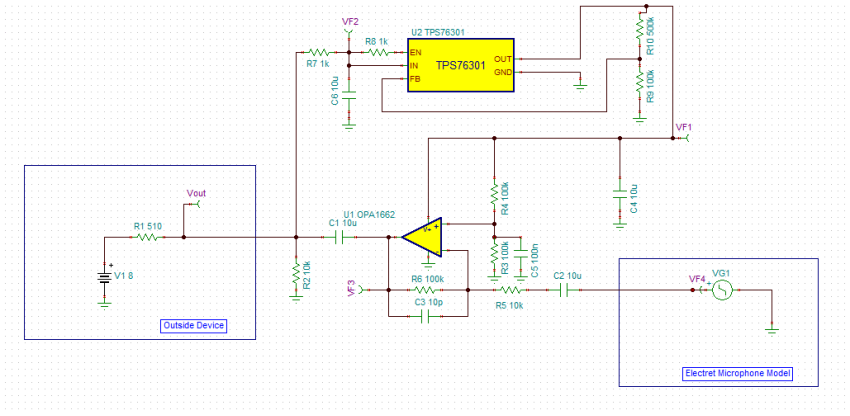
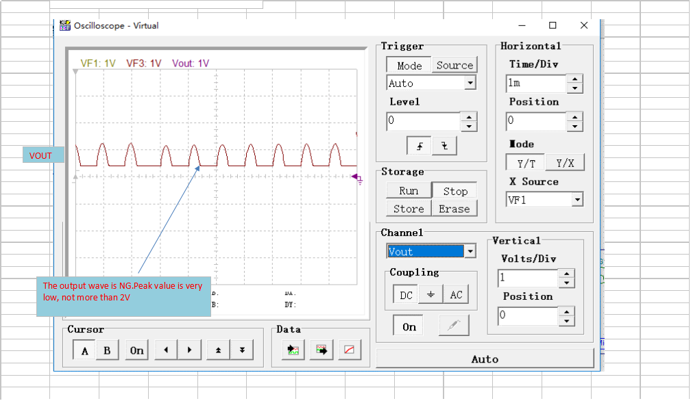
    I use OPA1662 make simulation, But it didn't work very well. Peak value is very low, not more than 2V,  I want to get to 4V.   TSC File see attachment:Phantom-TINA-TI-tps76301 op1662.TSC

    The schematic diagram is as follows:

    The simulation waveforms are as follows:

  • Hi Alex,

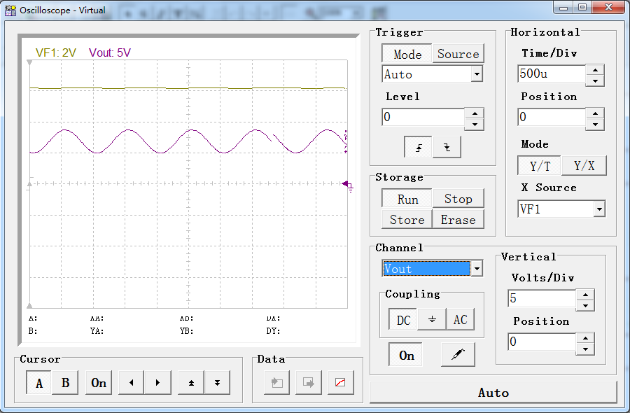
    I use NJM4558 make simulation, effect is ideal, the peak-peak value can reach 4V.  Phantom-TINA-TI-tps7601-NJM4558.TSC

    Please help to analyze the cause, thanks.

  • Hi Alex,
    Do you have any Suggestions? Thanks.