


Hi team,
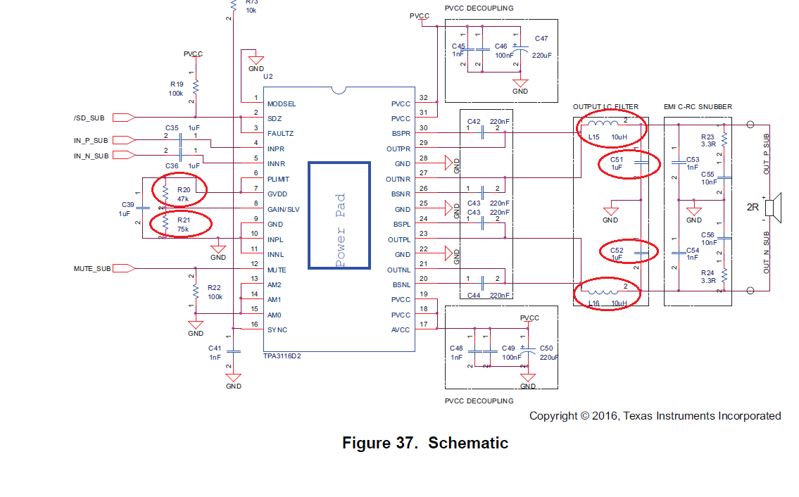
The customer is using TPA3116D2. He refers to U2 schematic in Figure 37 Schematic of the datasheet. He use one TPA3116D2 device.
The only difference is C51, C52 that are in U2 schematic in Figure 37 Schematic. The customer change C51 and C52 to 0.68uF.
Other parts are the same as U2 schematic in Figure 37 Schematic.
After he powers on his board, L15 and L16 that are in U2 schematic in Figure 37 Schematic are heat serious. R20 is 47K and R21 is 75K
in this case. When he changes R20 to 100K and R21 is 75K, L15 and L16 can be fine, but the speaker volume is reduced.
When he changes R20 to 75K and R21 is 47K, L15 and L16 can also be fine.
The U2 schematic is in the attach. Please check the attach.
The customer would like to know if he changes the R1 and R2 values, will this affect the circuit? Can the circuit worked well?
Best Wishes,
Mickey Zhang
Asia Customer Support Center
Texas Instruments
