This thread has been locked.

If you have a related question, please click the "Ask a related question" button in the top right corner. The newly created question will be automatically linked to this question.

PCM2912A: unable to play sounds with PCM2912A and IC also getting heat.

Part Number: PCM2912A

Hi team,

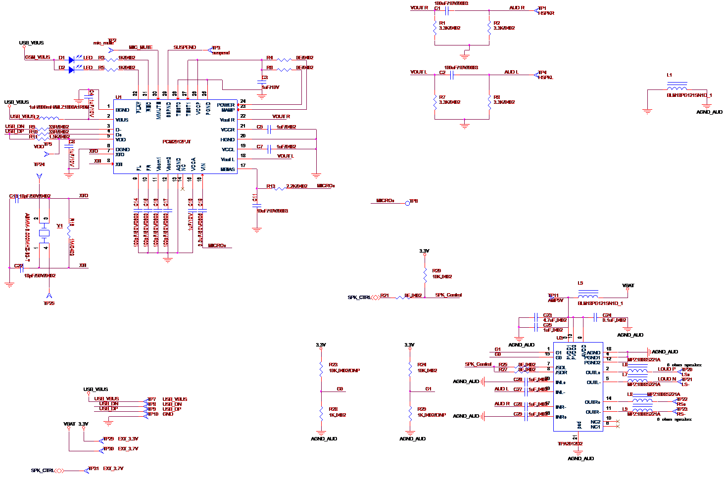
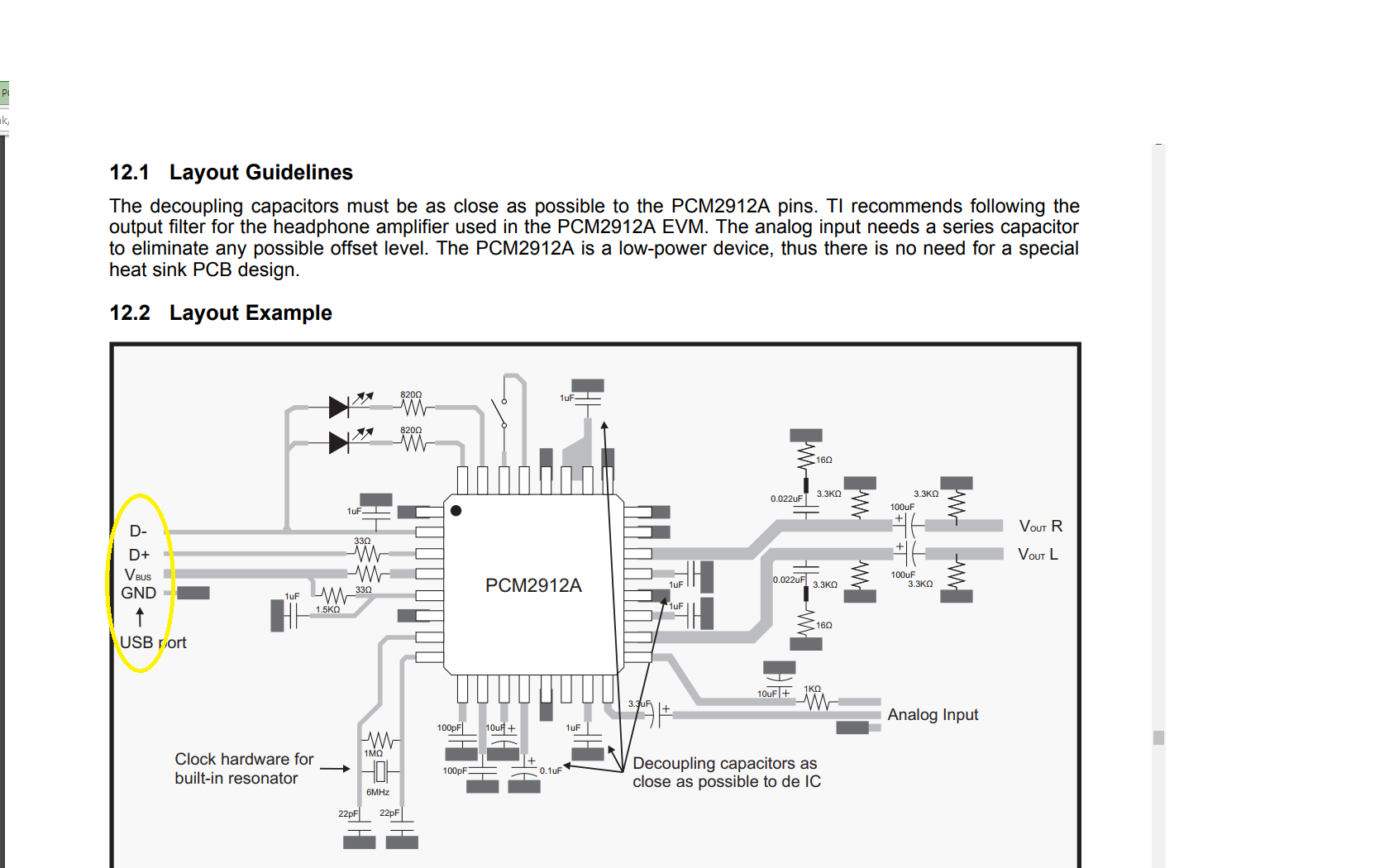
i designed a small PCB with PCM2912A and i am trying to play sounds from Windows 7 PC, i am not getting any sound there and PCM IC is getting very HOT when simly connected mode also, please guide me to resolve this here i pasted my schematic plz check that also.

  • Hi team,

    attached schematic.

    thanks,

    jack

  • Hi, Jack,

    This is not an expected behavior, the device should not get hot during normal operation. In general, the schematic of the PCM2912A seems fine, i noticed that there is a point where the node is not shown (between C3 and GND), can you please confirm that this connection is correct?. Also, can you please confirm the Xtal value?, it is not clear on the schematic if it is a '6' or '8'. Have you tried replicating the issue in a different board or with ah different IC?.

    Best Regards,

      -Diego Meléndez López
       Audio Applications Engineer

  • Hi Diego,

    Thanks for your reply,

    The C3 connection is okay one end connected to GND and other VCCP, and the crystal i am using 6Mhz only and the part number is ABMM-6.000MHZ-B2-T, cloud you please check crystal connections i connected 1st pin to Xin and 3 rd pin to Xout and 2,4 NC's this connection is okay with that crystal part or anything need to do? and i tested different PCB also for that also same problem(IC heating and not detected when i connected to windows PC).

    is this PCM ic is factory programmed  or any thing need to do, to detect in windows 7 PC directly when i am connected?

    Thanks,

    Jack

  • Hi Diego,

    issue: IC getting heat and not detected:

    Tested the voltage levels and VBUS = 5V i am giving and i am getting 3.3V at VCCP , VCCA and i am getting 0 .8V only at FL , FR , Vcom1 and Vcom2 and at SSPND pin 0V i observed but generally that pin should be high that i am not getting, i think this observation is bit helpful to trace out the issue ,please help me to resolve this.

    i am using this crystal ABMM-6.000MHZ-B2-T and voltages i observed .6V only at 1 and 4 pins of crystal.

    Thanks,
    Jack.
  • Hi, Jack,

    Thanks for the additional feedback. This device doesn't require any special programming or driver as it uses the native USB Audio codec driver from the used operating system. If the device is properly setup, it should be able to operate normally once connected to a USB bus.

    Crystal connection seems fine, have you verified that the actual clock is coming from it?.

    Voltage in VcomX pins is not correct, have you monitored VoutX pins as well? It seems that the device is not starting correctly, and the internal voltage regulation is not working.

    I also noticed that the caps on the VcomX pins are quite small, we recommend to use a 3.3µF for Vcom1 and  0.1µF for Vcom2.

    Another thing to try would be to remove or disconnect the amplifier, then try to probe the codec output and see if the issue is still occurring.

    As mentioned before, this is not an expected behavior for this device, so there is something wrong that is causing the IC to get hot.

    Best Regards,

      -Diego Meléndez López
       Audio Applications Engineer

  • Hi Diego,

    Yes,I measured the VoutR & VoutL voltages there i am getting n varying 1.0V to 1.1 V and I changed the cap values at VcomX as per your suggestion  after that also facing same problem and i was not mounted the amplifier section for all  these observations. i simply connected PCM IC and related capacitors, then also IC getting heat, this is vary serious issue for me please help me to resolve this.

    thanks,

    Jack.

  • Hi Diego,

    One more thing I observed guide lines for layout section in datasheet D-,D+,VUSB are connected to 2,3 and 4th pins respectively but in pin diagram there is a difference, please check it once in below attached image.

    and one more thing i observed that when i powered ON the board i am getting 3.3V at VccX pins that's Ok but after power OFF the board i immediately checked the continuity between VccX pins to GND it showing short but after some time it not showing the continuity between those pins.

    as per my understanding this is the reason IC getting heat(that means current flowing directly to GND from internal 3.3V regulator at ON time nothing but high leakage current   ) and i tested 4 IC's and getting  same issue and I'm suspecting that : is there any possibility to receive  damaged IC's LOT (non functional IC's) from TI.

    Thanks,

    Jack


  • Hi, Jack,


    Thanks for the feedback. The USB signals mentioned in the layout example diagram are incorrect, we will update the Datasheet to fix it.
    The behavior you are mentioning is not common, as long as your ICs were purchased from one of our authorized distributors, no issue is expected. Do you have an EVM that you can use to test the ICs with the issue?.
    I don't think that a layout issue is the reason, but I am interested in reviewing it before concluding that, can you share it?.

    Best Regards,

      -Diego Meléndez López
       Audio Applications Engineer

  • Dear Diego,

    Ok, please update the datasheet.

    I will share the Gerber no problem, please drop me a test mail to this email ID: jack.innovation9@gmail.com and I have the EVM, today i will replace the IC and update you the results.

    thanks,

    Jakkireddy.