This thread has been locked.

If you have a related question, please click the "Ask a related question" button in the top right corner. The newly created question will be automatically linked to this question.

Linux/TLV320AIC32X4SW-LINUX: TLV320AIC3204

Part Number: TLV320AIC32X4SW-LINUX

Tool/software: Linux

Hello,

I have two questions:

1) can I use the same I2S for input and for output simultaneously or should I used different ports?

2) Where can I get the configuration required to set up the routs for the ALSA framework?

Regards,

Igal

  • Hi, Igal,

    Welcome to E2E, Thanks for your interest in our products!.

    Yes, the I²S bus is composed of a word clock, a bit clock, a digital input and a digital output, so the same port can receive and send digital data simultaneously.

    Unfortunately we are no actively supporting Linux integration for these devices, we have a FAQ article avalable where you can find the information we have.

    Best Regards,

      -Diego Meléndez López
       Audio Applications Engineer

  • Hi,

    I'd like to configure the tlv320aic32x4 to operate as a playback slave (DAC):

    MCLK = 12MHz

    WCLK = 44100[Hz]

    BCLK = 1.4112[MHz]

    where all clocks are external to the CODEC. how should it be configured?

    Regards.

  • Hi, Igal,

    This is a common application where the device is getting configured in Slave mode, however, a consideration with the MCLK should be taken into account as 12MHz is not a common audio MCLK . Can you please confirm the MCLK frequency and the origin of this clock?. Please take a look at this app note where more information about the recommended clocking structure for audio applications with codecs is included.

    I would recommend you to take a look to the Applications Reference Guide of the 'AIC3204, where you can find several configuration scripts for the DAC that could be used as reference.

    From your clock settings, please consider that the data word length for the audio interface should be set to 16 bits, and the clock divider settings should be adjusted for 12MHz. I can help with the clock settings, but first I would like to know the details mentioned before about the MCLK.

    Best Regards,

      -Diego Meléndez López
       Audio Applications Engineer

  • Diego, hi,
    my host is a Jetson TX2 which is operated with the Linux OS. The embedded driver which was written for Linux limits the MCLK for 12[MHz], 24[MHz] or 25[MHz], thus I had to use this clock (I really do not know why these non standard MCLK clocks were selected). The other clocks are also driven by the Jetson to the tlv320aic32x4. It is possible that I'll eventually replace the MCLK to a more convenient clock but this will require to modify the driver .

    Regards,
    Igal
  • Diego, hi,

    Could you please provide the script for the above situation?

    Regards,

    Igal

  • Hi, Igal,

    For the clocking description provided before, I would recommend to use the bit clock as the source for the internal clock on the device. Please refer to below configuration code for the clock settings of the device according to the provided clocks.

    ###############################################
    # Clock Settings
    # ---------------------------------------------
    # The codec receives: MCLK = 12 MHz,
    # BLCK = 1.4112 MHz, WCLK = 44.1 kHz
    ###############################################
    #
    # Select Page 0
    w 30 00 00
    #
    # PLL_clkin = BCLK, codec_clkin = PLL_CLK,
    # PLL on, P=1, R=2, J=32, D=0000
    w 30 04 07 92 20 00 00
    #
    # NADC = 4, MADC = 4, dividers powered on
    w 30 12 84 84
    #
    # AOSR = 128
    w 30 14 80
    #
    # NDAC = 4, MDAC = 4, dividers powered on
    w 30 0b 84 84
    #
    # DOSR = 128
    w 30 0d 00 80
    #
    ###############################################

    Best Regards,

      -Diego Meléndez López
       Audio Applications Engineer

  • Diego, hi,

    thanks for the script I have configured the CODEC per the script though I cannot hear any sound from speakers which are connected to the line out. I can see signal in DIN, WCLK, BCLK.

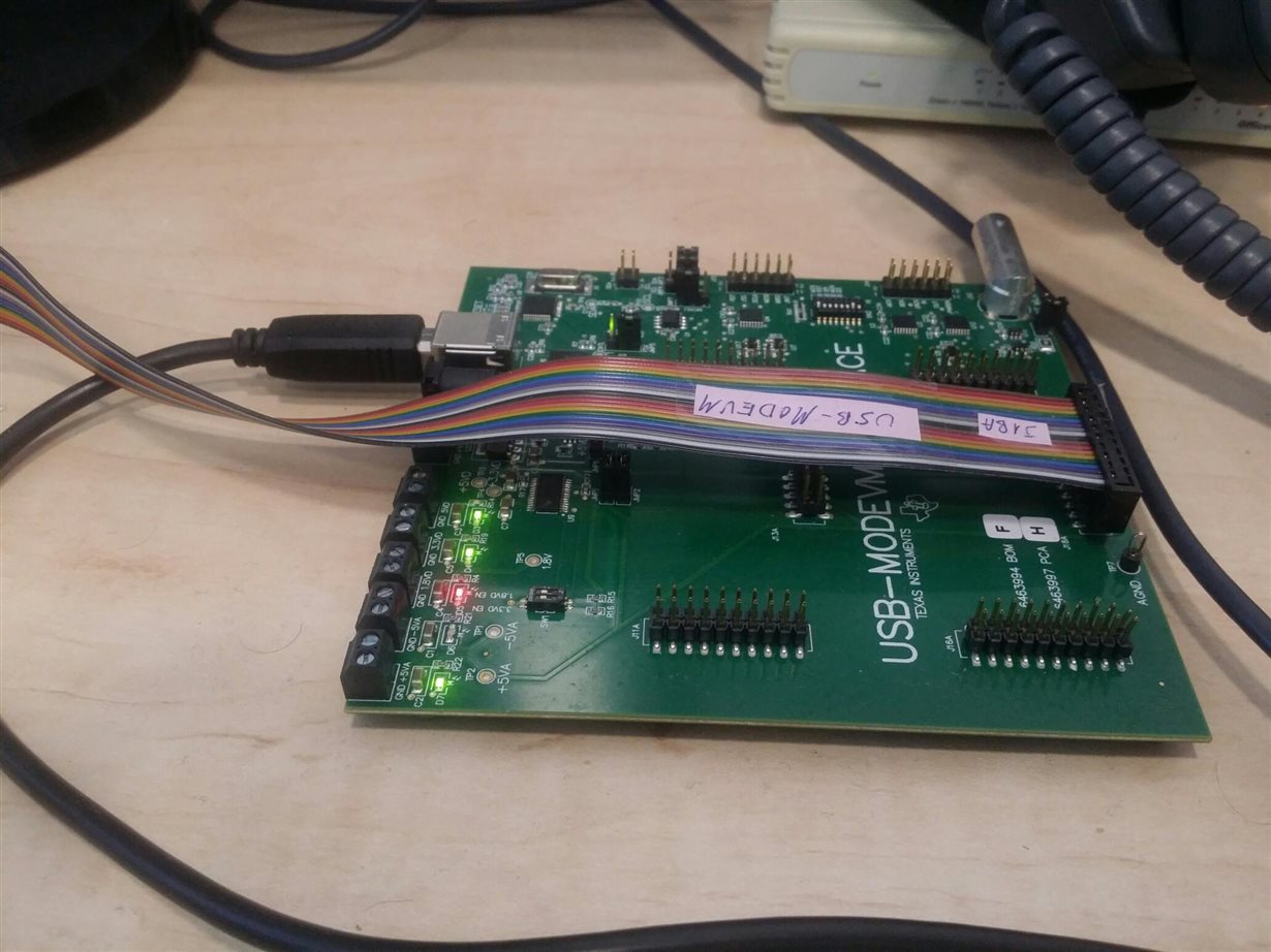
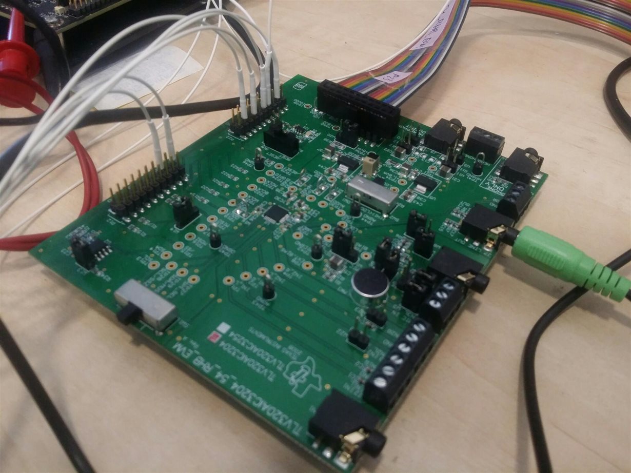
    I have also attached a picture of my setup.

    Please advise.

    Regards, Igal

  • Diego, hi,

    I had to activate the LOL and LOR and no I can hear the playback but with a lot of noise. Could you please let me know how to resolve it?

    Regards, Igal
  • Diego, hi,
    I had to shut down the MAL and MAR to reduce most of the noise, though the sound is not clear and a bit noisy.
    Any suggestions?

    Regards, Igal
  • Dieg, hi,

    Eventually I made it work by reducing the amplification in registers Left/Right DAC Channel Digital Volume Control Register (registers 65 and 66). Now a perfect sound is being played.

    Though something is problematic in this setting: The I2S channel has data input line and data output line which share the same bit clock and frame clock. The Master clock is not utilized. This means that If D2A and A2D is required from the CODEC on the same I2S interface then it will only work when D2A is applied, unless the Master Clock is utilized. Am I correct?

    Regards, Igal.

  • Diego, hi,

    I have rerun the system with the same configuration as yesterday and the noise is back. Could you please assist to identify the source of the noise?

    Regards, Igal
  • Hi, Igal,

    Thanks for the feedback. I am out of the office right now, but will take a detailed look to your comments and will get back to you in the next couple of days.  

    Best Regards,

      -Diego Meléndez López
       Audio Applications Engineer

  • Diego, hi,

    could you please help me with the noise and encoding issues?

    Regards, Igal

  • Hi, Igal,

    Sorry for the delayed response, I have been busy lately. I was looking at your setup and have a couple comments.

    Why are you using the codec disconnected from the USB-MODEVM? if you are using the 'AIC3204 codec as master and want to interface with an extenal system, it is possible to use the header J14 of the motherboard to hook external I²S signals, you only need to change the settings of SW2 so USB MCLK and USB I2S bits are set to off.

    The noise on the line output could be related to the register settings used, can you please share the settings used?. If reducing the gain helps with the noise issue, it is possible that the I²S signal is saturated. Have you tried the playback scripts from the applications reference guide I suggested before?.

    DIN and DOUT are part of the same I²S bus, where bit clock and word clock are shared. The internal clock is generated form the bit clock in this application, so it should be provided at all times. I don't think there should be a problem with your application unless you have different I²S interfaces for A2D and D2A, which is uncommon for general applications.

    Best Regards,

      -Diego Meléndez López
       Audio Applications Engineer

  • Diego, hi, thanks for the reply.

    1. I have connected the boards this way to provide an external I2C control. Is there a way to provide I2C control when both boards are connected?
    2. The registers are detailed hereafter.
    3. Yes I have tried them first. and I as I said it worked but the next day it did not.
    4. Simultaneous encoding decoding - thanks.
    00: 00
    01: 00
    02: 60
    03: 00
    04: 07
    05: 92
    06: 20
    07: 00
    08: 00
    09: 00
    0a: 00
    0b: 84
    0c: 84
    0d: 00
    0e: 80
    0f: 02
    10: 00
    11: 08
    12: 84
    13: 84
    14: 80
    15: 01
    16: 00
    17: 04
    18: 00
    19: 00
    1a: 01
    1b: 00
    1c: 00
    1d: 00
    1e: 01
    1f: 00
    20: 00
    21: 00
    22: 00
    23: 00
    24: 00
    25: cc
    26: 11
    27: 00
    28: 00
    29: 00
    2a: e0
    2b: 00
    2c: 00
    2d: 00
    2e: 00
    2f: 00
    30: 00
    31: 00
    32: 00
    33: 00
    34: 00
    35: 12
    36: 02
    37: 02
    38: 02
    39: 00
    3a: 00
    3b: 00
    3c: 01
    3d: 01
    3e: 00
    3f: d4
    40: 00
    41: 00
    42: 00
    43: 00
    44: 6f
    45: 38
    46: 00
    47: 00
    48: 00
    49: 00
    4a: 00
    4b: ee
    4c: 10
    4d: d8
    4e: 7e
    4f: e3
    50: 00
    51: 00
    52: 88
    53: 00
    54: 00
    55: 00
    56: 00
    57: 00
    58: 7f
    59: 00
    5a: 00
    5b: 00
    5c: 00
    5d: 00
    5e: 00
    5f: 00
    60: 7f
    61: 00
    62: 00
    63: 00
    64: 00
    65: 00
    66: 00
    67: 00
    68: 00
    69: 00
    6a: 00
    6b: 00
    6c: 00
    6d: 00
    6e: 00
    6f: 00
    70: 00
    71: 00
    72: 00
    73: 00
    74: 00
    75: 00
    76: 00
    77: 00
    78: 00
    79: 00
    7a: 00
    7b: 00
    7c: 00
    7d: 00
    7e: 00
    7f: 00
    80: 00
    81: 00
    82: 60
    83: 00
    84: 04
    85: 00
    86: 00
    87: 00
    88: 00
    89: 0c
    8a: 00
    8b: 10
    8c: 00
    8d: 00
    8e: 08
    8f: 08
    90: 7a
    91: 7a
    92: 3a
    93: 3a
    94: 00
    95: 00
    96: 00
    97: 00
    98: 00
    99: 00
    9a: 00
    9b: 00
    9c: 00
    9d: 00
    9e: 00
    9f: 00
    a0: 00
    a1: 00
    a2: 00
    a3: 00
    a4: 00
    a5: 00
    a6: 00
    a7: 00
    a8: 00
    a9: 00
    aa: 00
    ab: 00
    ac: 00
    ad: 00
    ae: 00
    af: 00
    b0: 00
    b1: 00
    b2: 00
    b3: 00
    b4: 40
    b5: 00
    b6: 00
    b7: 40
    b8: 00
    b9: 00
    ba: 00
    bb: 8a
    bc: 8a

    Regards, Igal
  • Hi, Igal,

    Thanks for the feedback. You can connect the I²C signals from your controller on header J6 of the motherboard while the EVM is connected. I was looking at the registers provided but I am afraid there are registers missing, the codec register map is composed by different pages which includes 256 registers on each one, the registers you are sharing seems to be only for Page 0. Can you please just share the registers you are writing to the device, not the complete dump?.

    It is strange that the codec had worked good before and now it is not, This makes me think that is it possible that a clock error is happening. Can you please verify the signals connected from your system?. 

    Best Regards,

      -Diego Meléndez López
       Audio Applications Engineer

  • Diego, hi,
    The linux driver details in the header file registers 0-100 and then to access registers on page 1 it adds 128. and in the driver there is no access to register 0 which is the gate for changing pages. Do know the reason for this one?
    Igal
  • Diego, hi,
    Another thing that I have noticed when I tried to get the registers from the device. I set page 0 and then read 128 registers and printed them, then I set page 1 (writing '1' to register '0') and read 128 registers, the values of both sets where identical. Is there another way to select page?
    Regards, Igal
  • Diego, hi,

    I have figured out the registers issue, they are being handled by the kernel via the regmap mechanism.

    Hereafter is the list of registers which were mapped into the reg ( it is possible to extract more registers but for now it provides to print out all registers from page 0 and up to register 188 on page 1, please let me know if you need more registers). I am still facing the noise issue on the audio output:

    00: 01
    01: 00
    02: 60
    03: 00
    04: 07
    05: 92
    06: 20
    07: 00
    08: 00
    09: 00
    0a: 00
    0b: 84
    0c: 84
    0d: 00
    0e: 80
    0f: 02
    10: 00
    11: 08
    12: 84
    13: 84
    14: 80
    15: 01
    16: 00
    17: 04
    18: 00
    19: 00
    1a: 01
    1b: 00
    1c: 00
    1d: 01
    1e: 04
    1f: 00
    20: 00
    21: 00
    22: 00
    23: 00
    24: 88
    25: cc
    26: 11
    27: 00
    28: 00
    29: 00
    2a: e0
    2b: 00
    2c: 00
    2d: 00
    2e: 00
    2f: 00
    30: 00
    31: 00
    32: 00
    33: 00
    34: 00
    35: 12
    36: 03
    37: 02
    38: 02
    39: 00
    3a: 00
    3b: 00
    3c: 01
    3d: 01
    3e: 00
    3f: d4
    40: 10
    41: 00
    42: 00
    43: 00
    44: 6f
    45: 38
    46: 00
    47: 00
    48: 00
    49: 00
    4a: 00
    4b: ee
    4c: 10
    4d: d8
    4e: 7e
    4f: e3
    50: 00
    51: 00
    52: 88
    53: 00
    54: 00
    55: 00
    56: 00
    57: 00
    58: 7f
    59: 00
    5a: 00
    5b: 00
    5c: 00
    5d: 00
    5e: 00
    5f: 00
    60: 7f
    61: 00
    62: 00
    63: 00
    64: 00
    65: 00
    66: 00
    67: 00
    68: 00
    69: 00
    6a: 00
    6b: 00
    6c: 00
    6d: 00
    6e: 00
    6f: 00
    70: 00
    71: 00
    72: 00
    73: 00
    74: 00
    75: 00
    76: 00
    77: 00
    78: 00
    79: 00
    7a: 00
    7b: 00
    7c: 00
    7d: 00
    7e: 00
    7f: 00
    80: 00
    81: 00
    82: 00
    83: 00
    84: 00
    85: 00
    86: 00
    87: 00
    88: 00
    89: 0c
    8a: 00
    8b: 10
    8c: 00
    8d: 00
    8e: 08
    8f: 08
    90: 7a
    91: 7a
    92: 3a
    93: 3a
    94: 00
    95: 00
    96: 00
    97: 00
    98: 00
    99: 00
    9a: 00
    9b: 00
    9c: 00
    9d: 00
    9e: 00
    9f: 00
    a0: 00
    a1: 00
    a2: 00
    a3: 00
    a4: 00
    a5: 00
    a6: 00
    a7: 00
    a8: 00
    a9: 00
    aa: 00
    ab: 00
    ac: 00
    ad: 00
    ae: 00
    af: 00
    b0: 00
    b1: 00
    b2: 00
    b3: 00
    b4: 00
    b5: 00
    b6: 40
    b7: 00
    b8: 00
    b9: 40
    ba: 00
    bb: 80
    bc: 80

    Regards, Igal.

  • Diego, hi,

    I think that the problem was the penetrating MCLK which is not utilized in the proposed sampling solution, where the BCLK is the sources of the PLL. Is there a way to filter out the MCLK?

    Regards, Igal
  • Hi, Igal,

    Sorry for the delay, the last couple of days I was in holiday.

    The MCLK should not affect the internal clocking scheme as long as it is disconnected from the PLL, for your configuration you can remove the master clock from the device without issue as long as the BCLK is valid and is configured as the source for the PLL (what seems correct from the register settings).

    Best  Regards,

      -Diego Meléndez López
       Audio Applications Engineer