This thread has been locked.

If you have a related question, please click the "Ask a related question" button in the top right corner. The newly created question will be automatically linked to this question.

TAS5720A-Q1: Clock tolerances? SCLK, MCLK, LRCLK?

Part Number: TAS5720A-Q1

Hi,

I'm trying to get the Fs 16kHz, SCLK = 32*Fs, MCLK = 256*Fs mode working, which is permitted for single-speed, software-controlled mode in the datasheet.

Ideally this wants a 4.096 MHz MCLK, however my MCLK source is just plain 4.0 MHz (and all other clocks derived down from that),

meaning about 2.3% under ideal, although there is no frequency tolerance mentioned in the datasheet.

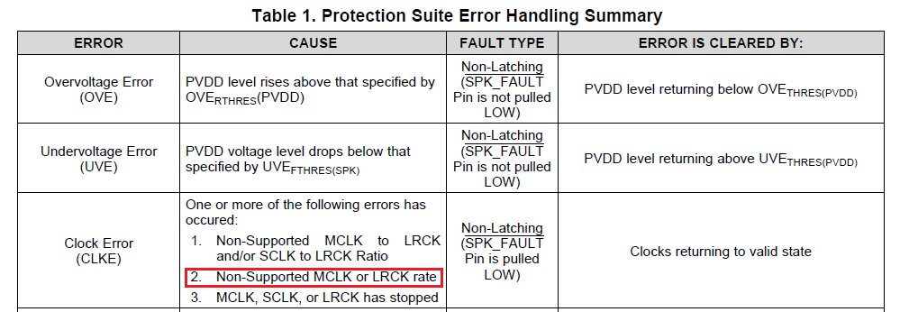
The part keeps giving me a steady CLKE error (bit 3 in register 8), which is supposed to be non-latching,

so it means the error is not recovering.

I've tried re-toggling /SPK_SD and reprogramming the registers after my clocks were already on, but this did not help.

(Possibly irrelevant info: although the part drives only one speaker, there is identical 16-bit I2S data in both I2S channels,

and I've tried but I've tried both BTL and PBTL settings but nothing changes).


  • Mike,

    Have you tried to inject the 4.096MHz signal and checked if the clock error goes away?

    Regards,

    -Adam
  • No, the part driving my I2S stream drives all the clocks and the data line and produces the 4.0 MHz MCLK

    I don't have a way to modify that.

    In the mean time we ordered the TI eval kit for the part. I'm hoping it has a working 16kHz mono example.

    I'm not trying to do anything fancier than that, and I really doubt that a -2.3% clock frequency error should cause a digital clocking error issue.

    This is what I see on my scope:

    MCLK: 4 MHz

    SCLK: 0.5 MHz

    LRCK: 15.625 kHz

    The register settings are:

    00->00

    01->FD (use FC to reset the device)

    02->14 (tried 13 and 15 also)

    03->80

    04->CF

    05->CF

    06->D1  (tried 51 also)

    07->00

    08->00 (I write 00, but it comes back 08 since there is the CLKE bit)

    09..0F all read as 00, I don't write them.

    10->FF

    11->FC

    reg 8 is always 08 no matter what I do

    Also, there is a contradiction in the datasheet:

    In table 10, for bit 3 it mentions sampling rates for single speed as only 32,  44.1, and 48 kHz

    But in Table 5, it shows seven supported sampling rates, all the way down to 12 kHz, so my 15.625-instead-of-16.000 kHz should not be an issue.

    Do you have an example of register settings for 16kHz mono?  Or can you see anything wrong with the settings I am using?

  • Hi Mike,

    First of all, I can confirm that TAS5720A-Q1 can support 16kHz. 

    I assume the MCLK to LRCK ratio in your system is 256 and the SCLK to LRCK ratio is 32, correct?  If these ratios vary, a clock error will be reported.

    In addition, it is very likely the LRCK rate (15.625kHz) is not accepted.  I would suggest you use a real 4.096MHz MCLK.

    Andy

  • So, as an experiment, I have doubled the frequency of the MCLK. It is now 8.0 MHz. Sclk (which is /8) is now at 1MHz, and LRCLK (which is /256) is now 31.25 kHz. The CLKE bit remains set. The problem is and was, evidently, NOT due to the 2.3% difference between 15.625 and 16.000 -- but due to something else.

    I've shown you my register settings (which don't work), now you show me yours (which you claim does work).
  • I found what was causing the issue.
    Despite there being a /SPK_SD bit in register 0x01, even in "software control mode" we really do need to force the hardware /SPK_SD pin low when programming I2C registers, then raise it high afterwards. Playing with the bit in register 1 is NOT the same thing, despite having the same name. I pulsed it low for 1ms before programming any registers and I now have working audio at 15.625 kHz.