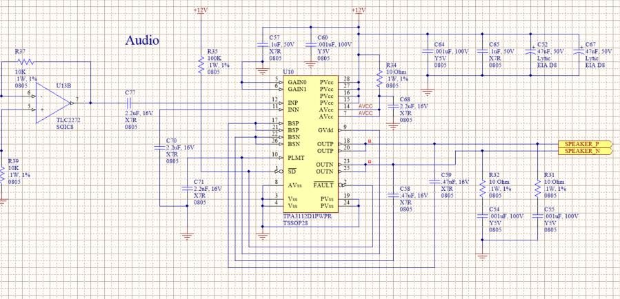
Hello Team,
Posting on behalf of customer. Please note that this circuit, minus the snubbers, has been used on two other products with no issues.
Thanks,
Keith N.
AFA OH/wPA
This Class D audio circuit has been in use here for quite some time, and as far as I knew, there was no problem with it. I used the same circuit on our newer product, but changed the output circuit to put ferrites as close as possible to the IC’s outputs. I also didn’t have the snubber circuits shown below. My concern was EMI. 150 built and tested boards and nobody has seen a failure.
We are rolling out a new project, and 1 in 85 controls is failing for audio. They work in the test and calibration stages of setup. Then at the final step, I think the audio is a bit louder, they quit working. No more audio. Not until power cycled. I have checked that audio is still present on the input.
The /FAULT pin goes low and stays low. I know the auto-retry is supposed to work…. When the fault pin goes low, it shuts the amp down (outputs stop PWM output immediately) but it doesn’t come out of shutdown. The pullup (R35 in this case) is 100K. Tried dropping to 1K… The voltage goes goes up a bit but does not restart.
I checked the 12V supply at the time of the fault (+/- a few hundred microseconds). There is no transient on the 12V line that could cause the chip to go into a funky mode of operation. I removed the snubber circuits from the design. No change. However, I noted that the output lines transient up to 19V with the loudspeaker connected.
After trying different measurements for a hour or so, the chip started failing more easily… before the final place in the test sequence that used to make them fail. This tells me that the chip is being damaged by the transients since it is failing more easily after so many events.
Is there anything that you can suggest, using the same circuit topology to fix this problem?


