This thread has been locked.

If you have a related question, please click the "Ask a related question" button in the top right corner. The newly created question will be automatically linked to this question.

PCM2900C: schematic review

Part Number: PCM2900C
Other Parts Discussed in Thread: PCM2900

Team,

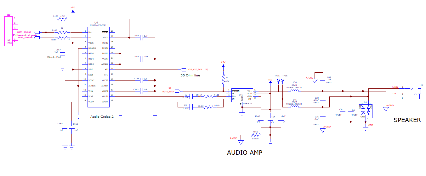
I have a customer with a prelim schematic using PCM2900C, driving a TPA6211 that drives a speaker. Can you guys check for an issues?

The cable from J5 to speaker is about 10 feet.  The speaker itself does not have an amplifier, and is 8ohm.   J0 is the USB interface.  


Thanks,

Brian

  • Hi, Brian,

    I have reviewed the Schematic of the PCM2900C, please refer to below comments:

    • The use of an external clock instead is possible, but some considerations must be taken, the clock should be running at all times, it is unhealthy for the device to stop the clock while the part is powered ON.
    • The values of the decoupling caps used are different from the recommendations of the datasheet typical applications section, I would recommend to use thee same decoupling cap values indicated in the datasheet.
    • Is the 5V supply the same as the USB bus? This part requires Vbus pin to be connected to the 5V of the USB bus to complete the internal power-on sequence.

    For the TPA6211, I would recommend you to post our schematic request in the Audio Amplifiers Forum, where one of my colleagues will be happy to help you.

    Best Regards,

      -Diego Meléndez López
       Audio Applications Engineer

  • Diego,

    I am speaking with the audio amps team, thanks. Regarding your concerns:

    For caps, I used the suggestion from the eval board, see user's guide page 10. You still recommend datasheet typical app circuit over eval board?


    The PCM2900 USB connects to NUC via a cable.  The power to DVR is ready before the NUC powers up.  So I have a 5V regulator for the Vbus instead of the Vbus for the NUC.  In another word, there is only D+/- and GND from NUC to PCM2900 and the Vbus is from the regulator on the DVR connector board.  What do you think?

    The clock point is a good one and I am doing it this way, is it good?  X1401 is divided and buffered:

    Thanks,

    Brian

  • Hi, Brian,

    Thanks for the feedback. It is fine to keep the cap values from the EVM, there should be no big issue.

    Regarding the Vbus situation, probably there would be no issue as long as the Vbus is provided before the USB bus reset occurs so the attach process is done properly according to Interface Sequence section of the datasheet.

    The clock generation seems fine, looks stable. Please consider that you need to make sure that the clock is provided during all the time the device  is operational. If there is a clock failure, the device will malfunction.

    Best Regards,

      -Diego Meléndez López
       Audio Applications Engineer