This thread has been locked.

If you have a related question, please click the "Ask a related question" button in the top right corner. The newly created question will be automatically linked to this question.

TLV320DAC3203: Enabling the Beep Generator

Part Number: TLV320DAC3203

I'm trying to test the DAC output by enabling the Beep..

I verified the 3.3v/1.8v are at the chip, and that it's not in reset.

The MClk (8Mhz) and BClk (1Mhz) also look good going to the DAC, where 1Mhz was chosen as approximately 16bits/ch * 2ch * 30kS/sec

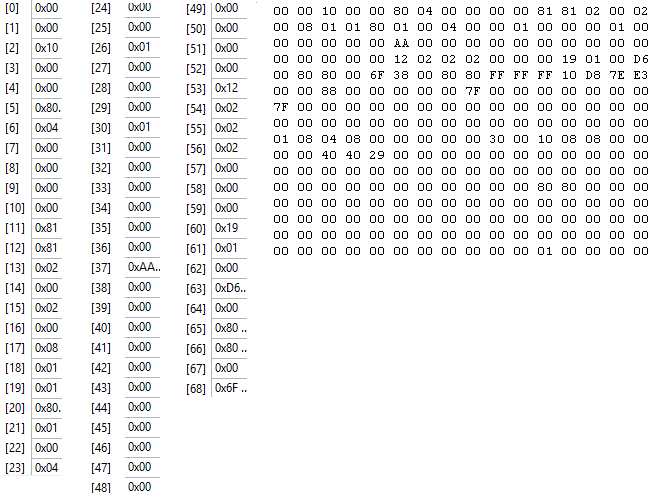
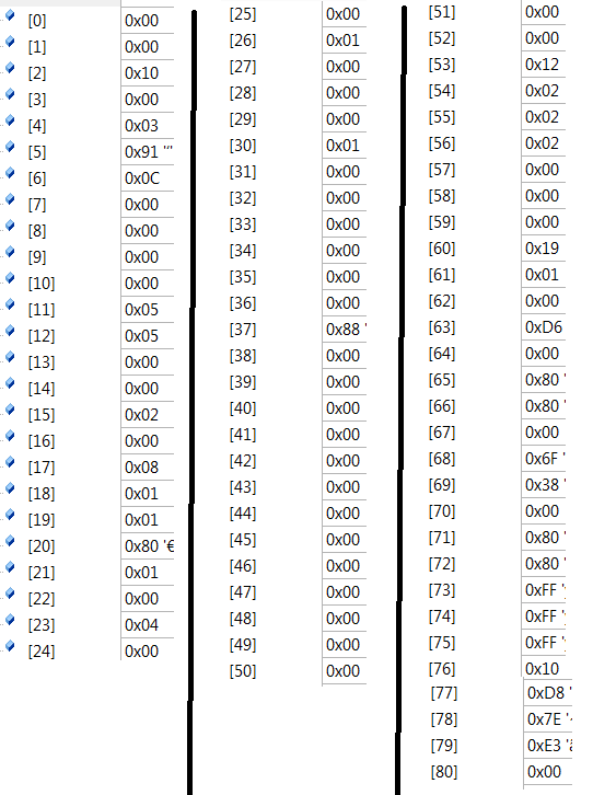
The register configuration follows the Example Setup 4.1, with the differences related to the Beep (ex. Processing Block P25 (Reg 0x3C = 0x19), Beep Length, Beep Enable*)

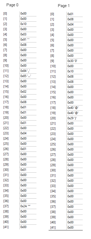
The readback of the registers match what I've written, however, there is no signal at the HPL/HPR pins..  the Beep Enable (Page 0 Register 0x47)  always reads back 0x80 and is not resetting automatically, so it seems like it's not running, but I can't see what's wrong. 

*Note, according to the Reference Guide, the Beep Enable is listed as being on Page 0, however in Section 2.4.5.1, it's described as being on Page 1.. I assume this is a typo in the document? 

  • Hi Parker,

    The person in charge of this device is out of the office. He will be responding the next week with further details.

    Best Regards
    José Luis Figueroa
    Audio Applications Engineer
  • Hi Lewis,

    I'll review this issue. However it might be related to the unusual clock frequencies. The beep generator is closely related to Fs, so special attention must be paid to the clock settings.
    I'll come back with details of my analysis on the issue.

    Best regards,
    -Ivan Salazar
    Applications Engineer - Low Power Audio & Actuators
  • Lewis,

    I have some questions about the clock setting registers (this is key for the beep generator as it is based on Fs).
    - Register 4 is set to 0x00. This means that MCLK is sent to CODEC_CLKIN, so PLL would not be used.
    - Register 5 is set to 0x80. This means that PLL is powered up, although Reg 4 implies that PLL should not be used. In addition R=0 which is not OK.

    So if you want to use MCLK = 8MHz and Fs = 30kHz you could set the device as follows:
    - MCLK pin is input to PLL
    - PLL Clock is CODEC_CLKIN
    - PLL powered up
    - PLL_P = 1
    - PLL_R = 1
    - PLL_J = 12
    - PLL_D = 0
    - NDAC = 5
    - MDAC = 5
    - DOSR = 128 (DOSR should be 128 for good device operation)

    Best regards,
    -Ivan Salazar
    Applications Engineer - Low Power Audio & Actuators
  • Thanks Ivan, I've got a power issue that I'm working thru, but afterwards I'll make those changes and post the results
  • Hi Parker,

    we haven't heard back from you, I am assuming that you were able to resolve your issue. If not, you just post a reply or create a new post if this one was closed due to time-out.

    Best Regards
    José Luis Figueroa
    Audio Applications Engineer
  • Thanks Jose, sorry for the delay, been working thru other issues with the board. I did try the settings as suggested but no luck seeing anything out of the Left/Right pins..

    // MCLK pin is input to PLL
    // PLL Clock is CODEC_CLKIN
    Write (PAGE_0, 0x4, 0x3);

    // PLL powered up
    // PLL_P = 1
    // PLL_R = 1
    Write (PAGE_0, 0x5, (1<<7) | (1<<4) | (1<<0));

    //PLL_J = 12
    Write (PAGE_0, 0x6, 12<<0);

    /PLL_D = 0
    Write (PAGE_0, 0x7, 0);
    Write (PAGE_0, 0x8, 0);

    // NDAC = 5
    // MDAC = 5
    // DOSR = 128
    Write (PAGE_0, 0xB, (1<<7) | ( 5<<0);
    Write (PAGE_0, 0xC, (1<<7) | ( 5<<0);
    Write (PAGE_0, 0xD, (128<<0);

    Doing a readback of the regs, it verifies the intended settings above, as well as having the beep generator bit enabled (0x47=0x80). I also see the 8Mhz MClk. Is there another register that might be the issue?

  • Lewis,

    What have you set to Page 0x01 Reg 0x09? What about Reg 0x0C and 0x0D from the same Page 0x01?
    You should completely configure the device in terms of clock and routing settings.
    From your read back I see that Page 0x00 Reg 0x25 is 0x88, which means that LDAC and RDAC are powered but HPL and HPR are not.

    Best regards,
    -Ivan Salazar
    Applications Engineer - Low Power Audio & Actuators
  • Interesting, sometimes I enable power to it, but the readback on Reg 25 shows 0x88..  perhaps it takes some time to turn on.

     I've had crazy power issues on the board, but I do see clean power at the chip   (3.3V IOVDD and  1.8V DVDD/AVDD/HPVDD).

  • Lewis,

    Have you checked the output? Any chance there could be a short at the output that leads the device into protection?

    Best regards,
    -Ivan Salazar
    Applications Engineer - Low Power Audio & Actuators
  • The output doesn't seem to be shorted to anything...   I do see a little blip when the command to turn on the output power is sent,  so it seems ok, except for there's never any wave.       Was there anything in the page 1 register dump that seems unusual?   Is the order in which the registers are written critical to the operation?