This thread has been locked.

If you have a related question, please click the "Ask a related question" button in the top right corner. The newly created question will be automatically linked to this question.

TLV320ADC3101: 16 KHZ sampling rate setting

Part Number: TLV320ADC3101

Dear, we have used TLV320ADC3101 for a mic array project and met some problem now.

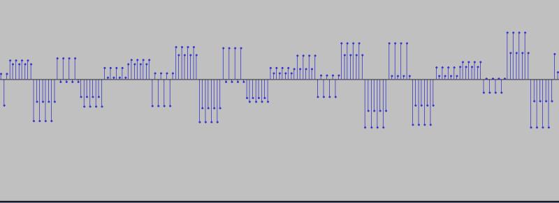
Our desired sampling rate is 16KHZ, and we can record but seems the PCM data is abnormal. Pls help to check and comment.

our clock setting, we didn't input MCLK

BCLK input :1.024MHZ

LRCK input:16KHZ

desired DOUT: left-justified, 32bit, 16KHZ

  • Hi,

    The issue might be related to an incorrect clock setting or digital audio format. Can you please share the register settings used to configure the part?. Also, having more information about the intended audio format and number of channels used would be very useful for us.

    Best Regards,

      -Diego Meléndez López
       Audio Applications Engineer

  • Dear  Diego:

    Thanks for your reply!

    We have fine tuned the register and the PLL configuration is correct now.

    BCLK: 1.024MHZ

    WCLK: 16KHZ

    didnot input MCLK, system can work now, the recording file is normal.

    but I have one more question, I think the PCM data has some DC voltage, I want to use a filter to remove it. Do you have any suggestions?

    Datasheet mentioned that 'A firstorder IIR filter is always available, and is useful to filter out possible dc components of the signal efficiently', so it can remove the DC voltage? How can I use it?

  • Hi,

    Thanks for the feedback. This is an expected behavior of this part as there is a small offset variation on the ADC; this variation  can be compensated by changing the values of Page 1 / Register 26: Dither Control. 

    Best Regards,

      -Diego Meléndez López
       Audio Applications Engineer

  • Dear Diego:

    this offset setting can approve a little, but I want to know if First-Order IIR filter can remove the DC completely? Thanks.

  • Hi,

    The first order IIR filter can be used to  help with the removal of DC components. In order to configure the filter, you need to generate the coefficients for the high pass filter of your choice (the TI biquad tool can be used) and write them into the corresponding register location, as described in section 10.3.12.3.1 of the datasheet.

    Best Regards,

      -Diego Meléndez López
       Audio Applications Engineer

  • Dear Diego:

    how to use the TI biquad tool?

    I chose the highpass filter, 16KHZ, 32bit and I got a file, so which parameter is N0,N1 and N2?

  • Hi,

    The TI Biquad tool generates the required coefficients as soon as they are generated with the graphical interface. On the Coefficients window, the text in the top will specify the filter type and the format for each type of filter. In the case of 1st order filters (1O), the three lines represent the three coefficients, N0, N1 and D1 respectively. The resolution specification is not the audio data size, it is the coefficient size for the biquads of a given device. For the 'ADC3101, the coefficient size is 16 bit. 

    For example, for the filter you are trying to accomplish, the coefficients would be:

    High Pass 1st Order Butterworth, 50 Hz Fc 0.0 dB 

    N0 = 0x7EC0
    N1 = 0x8140
    D1 = 0x7D81

    The coefficients generated should be written to the specific location indicated in section 10.3.12.3.1 of the datasheet.

    Best Regards,

      -Diego Meléndez López
       Audio Applications Engineer