This thread has been locked.

If you have a related question, please click the "Ask a related question" button in the top right corner. The newly created question will be automatically linked to this question.

TPA6111A2: Headphone amplifier single ended configuration, shorting feedback resistor and output coupling capacitor

Part Number: TPA6111A2

Hi,

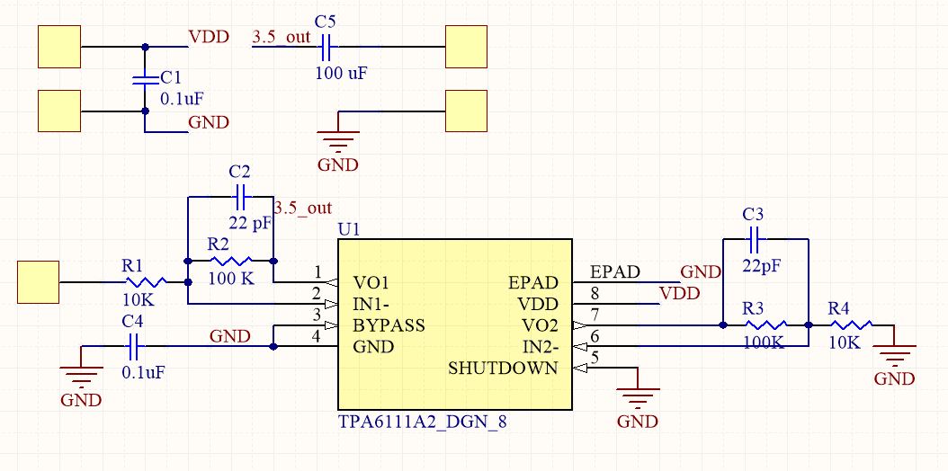
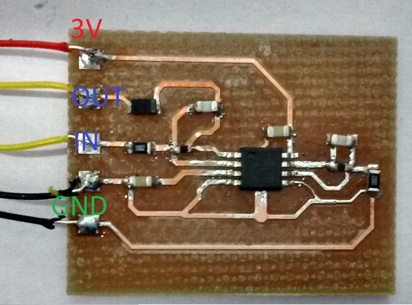
I am using TPA6111A2 as a headphone amplifier, in the single ended configuration. Do I have to short the feedback resistor and output coupling capacitor for the channel that is not being used. I have highlighted the parts with the red pen in the image pasted below. Does TI have mono headphone amplifier. I am not able to find one.
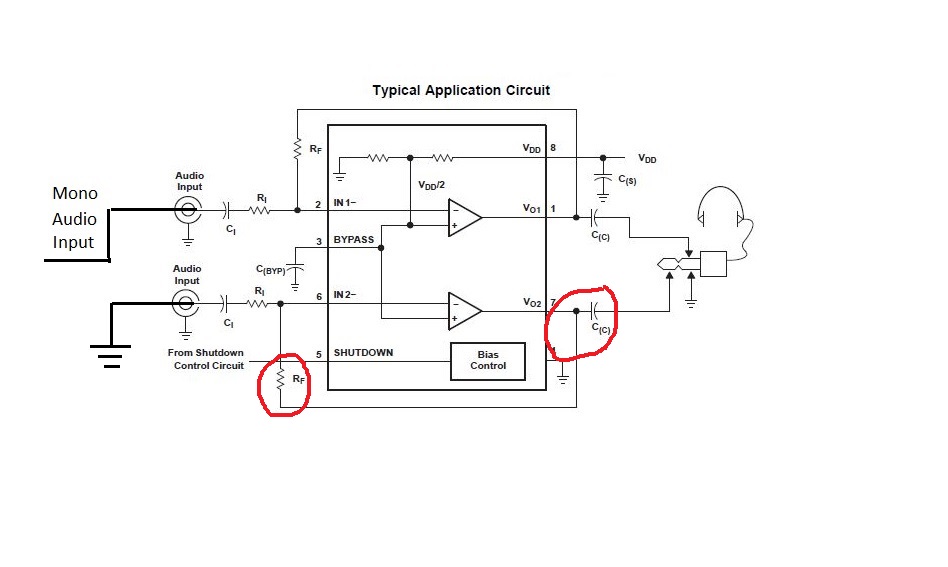
Regards,

Tapas 

  • Hi Tapas,

    Hhm, you want to use only one channel and want to know how to wire the unused channel?

    I would mount identical Ci, Ri and Rf for both channels and short the unused input to ground, like you have drawn it. Then I would use C(c) only for the used channel. Don't mount C(c) for the unused channel and don't connect the output of unused channel to anything.

    Kai
  • Hi Tapas and Kai,

    Thanks, both for sharing this information.

    Best Regards
    José Luis Figueroa
    Audio Applications Engineer
  • Hi,

    I have made the PCB of the single ended configuration, but it is not working at all. I am giving 100 mVpp through function generator, but in the output I am not receiving any signal. Please help me with this.

    Regards,

    Tapas

  • Ci forgotten?
  • Hi Tapas,

    It seems that you forgot to place the input capacitors. You could add them and see if this helps.

    Best Regards
    José Luis Figueroa
    Audio Applications Engineer
  • Hi kai & José ,

    It is working fine after adding input coupling capacitors, thank you very much. I don't know how, I forgot to add input coupling capacitor (such a silly mistake). I am just curious, coupling capacitor removes DC off set, but I was using function generator which does not have any DC off set, then why it did not work. 

    I have two queries.

    1) In the datasheet it is written "For values of RF above 50 kΩ, the amplifier tends to become unstable due to a pole formed from RF and the inherent input capacitance of the MOS input structure. For this reason, a small compensation capacitor of approximately 5 pF must be placed in parallel with RF"

    In my case, I am using 22 pF capacitor and it is working fine, do I have use 5 PF capacitor only or 22 pF that I am using will do fine. If I remove any compensation capacitor, what will the consequence of that?

    2) The output coupling capacitance that I am using is 100uF to get lower frequency. I am giving the output from this to a microphone input jack (* link below). But if I connect headphone (16 Ohm impedance) the minimum frequency that we will get is 99.47 Hz. But If we want lower frequency (20 Hz) then, I have to use capacitance up to 500 uF. Can I use such big capacitor to get lower frequencies. How does commercially available system solve this problem, to get lower frequencies.

    www.amazon.in/.../ref=sspa_dk_detail_0

    Regards,

    Tapas 

  • Hi Tapas,

    this compensation cap is necessary because the parasitic input capacitance of chip is eroding the phase margin by introducing a phase lag in the feedback path. But this is only a problem if Rf is high ohmic. The 5p cap recommended is the minimum capacitance which is needed to add enough phase lead in the feedback path to restore the phase margin and by this to improve the stability.

    You can also take a 22p cap. This will be perfect. When omitting this compensation capacitance the amplifier can start to oscillate. This is the more probable the more load capacitance is placed to the output. So, when cables are mounted to the output the amplifier can easily become unstable. Even if you don't use a cable it's nevertheless wise to use this compensation capacitance!

    You can increase the output capacitance. But read section 10.2.2.5 of datasheet. I think that a corner frequency of 40Hz (-3dB) is totally sufficient.

    Kai
  • Hi Kai,

    Thanks for your comprehensive reply.

    According to the datasheet compensation capacitor should be approximate 5 pF, but I am using 22 pF which is about 4 times larger than the recommended value, will it not cause any issues. Is there any calculation which shows, it should be about 5 pF.

    Regards,

    Tapas
  • Hi Tapas,

    datasheet does not provide enough information to calculate this in detail. The parasitic input capacitance and the open loop output impedance would be needed. But a simple phase response simulation of the feedback loop can demonstrate what's going on.

    You see that without compensation capacitance a phase lag in the feedback look is dominating. The minus sign tells this. With a 5pF compensation cap the phase lag is partially compensated by the phase lead introduced by the 5pF cap. The resulting phase lag is only 12° instead of 70° without the compensation cap. This is just the difference between "stable" and "unstable". With the 22pF compensation cap there's even more phase lead added so that the resulting phase is no longer negative.

    There's no need to increase the compensation cap from 5pF to 22pF. But it doesn't harm, too.

    Kai