This thread has been locked.

If you have a related question, please click the "Ask a related question" button in the top right corner. The newly created question will be automatically linked to this question.

TLV320AIC3104: I2S TDMS-Configuration and BCLK as PLL-Source doesn't work

Part Number: TLV320AIC3104
Other Parts Discussed in Thread: TLV320AIC33

Hello,

I have a communcation problem concerning I2S between a telit LE910-Module and the AIC3104 codec.

The i2c configuration interface, also a loopback configuration from LINE1LP to LEFT_LOP work fine.

My aim is to read a mono signal single ended from LINE1LP to I2S-Interface, and from I2S-Interface to LEFT_LOP single ended.

The I2S-configuration of the LE910-Master is:

Mode: TDMS

BCLK: 4096 kHz

Sample rate: 16 kHz

WCLK: 16 kHz highpulse for 1 BCLK-Clock with 256 Clocks per frame.

Bits per Sample: 16

The signal level ist 1.8V

I  tried the following configuration

#!/bin/bash

# I2C-Busse suchen
modprobe i2c-dev

# Register 1: Software Reset Register
i2cset -y 7 0x18 0x01 0x80

sleep 1

# Register 102: Clock Generation Control Register: CLKDIV_IN uses BCLK, PLLCLK _IN uses BCLK
i2cset -y 7 0x18 0x66 0x62


####################################################################################################
# High speed mode: BCLK *  1 => J=24,D=0,R=1,P=1 (generate 12288 kHz internal clock from 4096kHz BCLK, fsref=48kHz, fs=16kHz)

#  Page 0/Register 2: Codec Sample Rate Select Register (Sample-Rate fs=fsref/3)
i2cset -y 7 0x18 0x02 0x44

# Page 0/Register 3: PLL Programming Register A (PLL enable, P=1, Q=16)
i2cset -y 7 0x18 0x03 0x81

# Page 0/Register 4: PLL Programming Register B (J=24)
i2cset -y 7 0x18 0x04 0x60

# Page 0/Register 5: PLL Programming Register C (D=0)
i2cset -y 7 0x18 0x05 0x00

# Page 0/Register 6: PLL Programming Register D (D=0)
i2cset -y 7 0x18 0x06 0x00

# Page 0/Register 11: PLL Programming (R=1)
i2cset -y 7 0x18 0x0B 0x01

# Page 0/Register 9: Audio Serial Data Interface Control Register B DSP-Mode, 256 Bit, ADC-, DAC-Resync)
i2cset -y 7 0x18 0x09 0x4E

####################################################################################################

# Page 0/Register 19: MIC1LP/LINE1LP to Left-ADC Control Register
i2cset -y 7 0x18 0x13 0x04

# Page 0/Register 15: Left-ADC PGA Gain Control Register (Unmute Left PGA, set gain to 0 dB)
i2cset -y 7 0x18 0x0f 0x00

# Page 0/Register 7: Codec Data-Path Setup Register (Route Left data to Left DAC)
i2cset -y 7 0x18 0x07 0x08

# Page 0/Register 37: DAC Power and Output Driver Control Register (Power up Left DAC)
# ? HPLCOM configured as independent single-ended output? 0xa0
i2cset -y 7 0x18 0x25 0x80

# Page 0/Register 41:  DAC Output Switching Control Register ( Left-DAC output selects DAC_L1 path to left line output driver.)
i2cset -y 7 0x18 0x29 0x00

# Page 0/Register 43: Left-DAC Digital Volume Control (Unmute Left digital volume control, set gain to 0 dB)
i2cset -y 7 0x18 0x2B 0x00

# Page 0/Register 82: DAC_L1 to LEFT_LOP/M Volume Control Register (Route Left DAC output to Left line outs)
i2cset -y 7 0x18 0x52 0x80

# Page 0/Register 86:  LEFT_LOP/M Output Level Control Register (0dB Gain Left line outs, LEFT_LOP power up)
i2cset -y 7 0x18 0x56 0x09

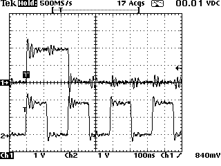
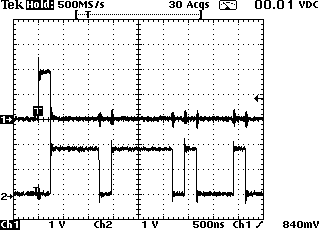
The result is, that I neither get samples from the input nore I found samples from the DIN at the LEFT_LOP.

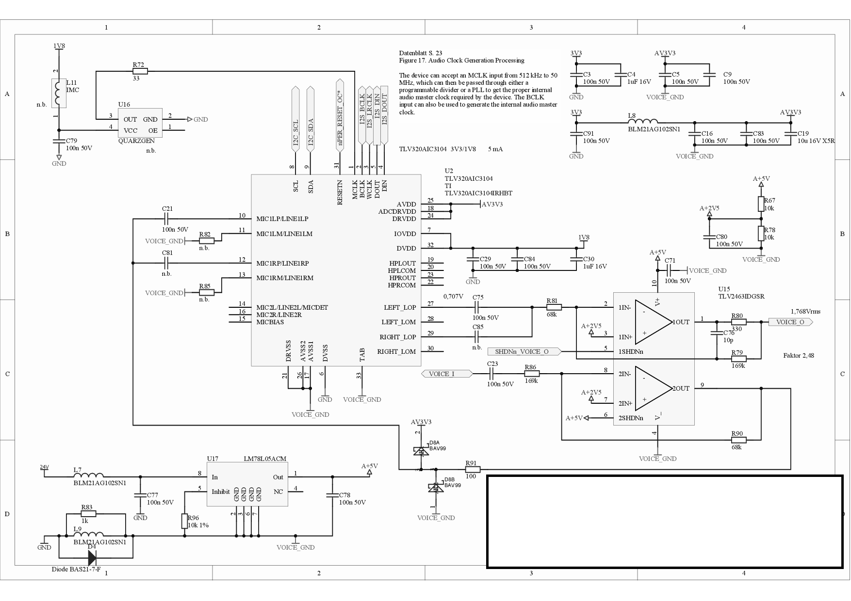
the schematic of the codec:

What is wrong with my configuration?

Kind regards

Gregor

  • Gregor, 

    I'm not seeing anything wrong with your configurations. 

    a few suggestions:

    1.  regarding your PLL configuration,  program all of the coefficients first, and then enable the PLL.  (register 3 should be programmed for the coefficients,  and PLL not powered up,  then all of the other PLL coefficients should be programmed, and finally Reg 3 can be written to again,  powering up the PLL)  This is probably not the cause of your problem, but It is our recommended sequence.

    2. can you check some of your status registers?  

    I2C status reg - 107

    ADC flags - reg 36

    Module power status - Reg 94

    best regards, 

    -Steve Wilson

  • Hello Steve,

    thank you for your help.


    I tried now the following skript:


    # I2C-Busse suchen

    modprobe i2c-dev


    # Register 1: Software Reset Register

    i2cset -y 7 0x18 0x01 0x80


    sleep 1


    # Register 102: Clock Generation Control Register: CLKDIV_IN uses BCLK, PLLCLK _IN uses BCLK

    i2cset -y 7 0x18 0x66 0x62


    ####################################################################################################

    # High speed mode: BCLK *  1 => J=24,D=0,R=1,P=1 (generate 12288 kHz internal clock from 4096kHz BCLK, fsref=48kHz, fs=16kHz)


    #  Page 0/Register 2: Codec Sample Rate Select Register (Sample-Rate fs=fsref/3)

    i2cset -y 7 0x18 0x02 0x44


    # Page 0/Register 3: PLL Programming Register A (PLL disable, P=1, Q=2)

    i2cset -y 7 0x18 0x03 0x11


    # Page 0/Register 4: PLL Programming Register B (J=24)

    i2cset -y 7 0x18 0x04 0x60


    # Page 0/Register 5: PLL Programming Register C (D=0)

    i2cset -y 7 0x18 0x05 0x00


    # Page 0/Register 6: PLL Programming Register D (D=0)

    i2cset -y 7 0x18 0x06 0x00


    # Page 0/Register 11: PLL Programming (R=1)

    i2cset -y 7 0x18 0x0B 0x01


    # Page 0/Register 3: PLL Programming Register A (PLL enable, P=1, Q=2)

    i2cset -y 7 0x18 0x03 0x91


    # Page 0/Register 9: Audio Serial Data Interface Control Register B DSP-Mode, 256 Bit, ADC-, DAC-Resync)

    i2cset -y 7 0x18 0x09 0x4E


    ####################################################################################################


    # Page 0/Register 19: MIC1LP/LINE1LP to Left-ADC Control Register

    i2cset -y 7 0x18 0x13 0x04


    # Page 0/Register 15: Left-ADC PGA Gain Control Register (Unmute Left PGA, set gain to 0 dB)

    i2cset -y 7 0x18 0x0f 0x00


    # Page 0/Register 7: Codec Data-Path Setup Register (Route Left data to Left DAC)

    i2cset -y 7 0x18 0x07 0x08


    # Page 0/Register 37: DAC Power and Output Driver Control Register (Power up Left DAC)

    # ? HPLCOM configured as independent single-ended output? 0xa0

    i2cset -y 7 0x18 0x25 0x80


    # Page 0/Register 41:  DAC Output Switching Control Register ( Left-DAC output selects DAC_L1 path to left line output driver.)

    i2cset -y 7 0x18 0x29 0x00


    # Page 0/Register 43: Left-DAC Digital Volume Control (Unmute Left digital volume control, set gain to 0 dB)

    i2cset -y 7 0x18 0x2B 0x00


    # Page 0/Register 82: DAC_L1 to LEFT_LOP/M Volume Control Register (Route Left DAC output to Left line outs)

    i2cset -y 7 0x18 0x52 0x80


    # Page 0/Register 86:  LEFT_LOP/M Output Level Control Register (0dB Gain Left line outs, LEFT_LOP power up)

    i2cset -y 7 0x18 0x56 0x09


    with the same result as before.


    I read back following values:


    Register 102: Clock Generation Control Register: CLKDIV_IN uses BCLK, PLLCLK _IN uses BCLK, soll: 0x62

    0x62

    Page 0/Register 3: PLL Programming Register A (PLL enable, P=1, Q=2), soll: 0x91

    0x91

    Page 0/Register 4: PLL Programming Register B (J=8), soll: 0x20

    0x60

    Page 0/Register 5: PLL Programming Register C (D=0), soll: 0x00

    0x00

    Page 0/Register 6: PLL Programming Register D (D=0), soll: 0x00

    0x00

    Page 0/Register 11: PLL Programming (R=1), soll: 0x01

    0x01

    Page 0/Register 9: Audio Serial Data Interface Control Register B DSP-Mode, soll: 0x40

    0x4e

    ####################################################################################################

    Page 0/Register 19: MIC1LP/LINE1LP to Left-ADC Control Register, soll: 0x04

    0x04

    Page 0/Register 15: Left-ADC PGA Gain Control Register (Unmute Left PGA, set gain to 0 dB), soll: 0x00

    0x00

    Page 0/Register 7: Codec Data-Path Setup Register (Route Left data to Left DAC), soll: 0x08

    0x08

    Page 0/Register 37: DAC Power and Output Driver Control Register (Power up Left DAC), soll: 0x80

    0x80

    Page 0/Register 41:  DAC Output Switching Control Register ( Left-DAC output selects DAC_L3 path to left line output driver.), soll: 0x40

    0x00

    Page 0/Register 43: Left-DAC Digital Volume Control (Unmute Left digital volume control, set gain to 0 dB), soll: 0x00

    0x00

    Page 0/Register 82: DAC_L1 to LEFT_LOP/M Volume Control Register (Route Left DAC output to Left line outs)

    0x80

    Page 0/Register 86:  LEFT_LOP/M Output Level Control Register (0dB Gain Left line outs), soll: 0x09

    0x0b

    Page 0/Register 36: ADC Flag Register, soll: 0xC0

    0x40

    Page 0/Register 94: Module Power Status Register, soll: 0x90

    0x90

    Page 0/Register 107:  New Programmable ADC Digital Path and I2C, soll: 0xC0

    0x00

    Page 0/Register 95: Output Driver Short-Circuit Detection Status Register, soll: 0x00

    0x00

    Page 0/Register 96: Sticky Interrupt Flags Register, soll: 0x00

    0x00

    Page 0/Register 97: Real-Time Interrupt Flags Register, soll: 0x00

    0x00


    Could it be a problem, that the BCLK runs only during a telephone call?

    So until now I make the configuration during BCLK and WCLK don't run.

    But I now also test to start a telephone call (BCLK and WCLK runing) and than make the coniguration and readback the register value.

    The result is exactly the same.

    It's curios, that the DC-Offset of LEFT_LOP is 2.5 V, in the evalutionboard it's 1.4V.

    During configuration it starts at 2.5V then goes slowly down during 1.2s until 1V and jumps back to 2.5V (measured at C75 codec side).


    The following signals are supplied to the codec:


    Channel 1: WCLK

    Channel 2: BCLK


    Channel  1: WCLK

    Channel 2: DIN (16 Bit/ sample)


     Channel  1: WCLK

    Channel 2: DIN (16 Bit/ sample, whole cycle)

     At the evaluation board, it makes a different if the Register R101, R102 are configured at the beginning, as you see in the following script code, or after configuring the pll. In the second case neither output LEFT_LOP nor Input LINE1LP works.

    i i2cfast
    #R7: SW Reset
    w 30 07 80
    #delay 1s
    delay 1000
    #BCLK=2,8224MHz, FSref=44,1 kHz, 16Bit, I2S
    #R102:  PLLCLK _IN uses BCLK
    w 30 66 22
    #R101: CODEC_CLKIN uses PLLDIV_OUT
    w 30 65 01
    #R3-R6: PLL disable, Q=2, P=1, J=32, D=0000
    w 30 03 11 80 00 00
    #R11: R=1
    w 30 0B 01
    #R3: PLL enable, Q=2, P=1
    w 30 03 91
    #R19: LINE1LP als ADC Input, 0dB
    w 30 13 04
    #R15:  The left-ADC PGA is not muted, 0dB
    w 30 0F 00
    #R9: not RMG I2S, 16Bit,Continus, offset=0, BCLK=In, WCLK=In
    w 30 09 00
    #R7:  not RMG, fS(ref) = 44.1 kHz, Left-DAC data path plays left-channel input data
    w 30 07 88
    #R37:  Left DAC is powered up
    w 30 25 80
    #R43: The left-DAC channel is not muted, 0dB
    w 30 2B 00
    #R41:   Left-DAC output selects DAC_L3 path to left line output driver.
    w 30 29 40
    #R86:  LEFT_LOP/M is not muted, 0dB,  LEFT_LOP/M is fully powered up
    w 30 56 09
    #Readback
    #R3-R6: PLL enable, Q=2, P=1, J=32, D=0000
    r 30 03 4
    #R11: R=1
    r 30 0B 1
    #R19: LINE1LP als ADC Input, 0dB
    r 30 13 1
    #R15:  The left-ADC PGA is not muted, 0dB
    r 30 0F 1
    #R9: not RMG, I2S, 16Bit,Continus, offset=0, BCLK=In, WCLK=In
    r 30 09 1
    #R101: CODEC_CLKIN uses PLLDIV_OUT
    r 30 65 1
    #R102:  PLLCLK _IN uses BCLK
    r 30 66 1
    #R7:  not RMG, fS(ref) = 44.1 kHz, Left-DAC data path plays left-channel input data
    r 30 07 1
    #R37:  Left DAC is powered up
    r 30 25 1
    #R43: The left-DAC channel is not muted, 0dB
    r 30 2B 1
    #R41:   Left-DAC output selects DAC_L3 path to left line output driver.
    r 30 29 1
    #R86:  LEFT_LOP/M is not muted, 0dB,  LEFT_LOP/M is fully powered up
    r 30 56 1

    Best regards


    Gregor

  • Gregor,

    what processor are you using? Is there a way we can switch the Mode of the codec to master and the processor to Slave? nothing obvious is popping out of your configuration.

    The common mode voltage on the LEFT_LOP should be like 1.4V. I'm not sure why you would measure such a high voltage, but that might explain why you aren't hearing anything.


    best regards,
    -Steve wilson
  • Hello Steve,

    since yesterday the codec works.

    The problem was, that in register R102 the input for CLKDIV_IN was configured to MCLK and this signal is open (the oszillator is not populated).

    I changed the register value to 0xA2. Now CLKDIV_IN is connected to BCLK.

    I didn't find any hind at the datasheet, the signal CLKDIV_IN has to be supplied with a clock.

    I have some more questions:

    1. At the datasheet chapter 10.3.4.4 "Audio DAC Digital Volume Control" is the function soft-stepping described. But I found settings in the registers only for the ADC-PGA R19, R22 and for the high power output R40. where could I find the soft-step-settings for the DAC?

    2. What is the meaning of the Re-sync function of R9?

    Best regards

    Gregor

  • Gregor,

    Im sorry I should've seen that. I was under the impression you were using the PLL, but I can see now that you select CLK_DIV for codec input. that would be why nothing works. If you select PLL_DIVOUT everything would function fine. If you want to use the CLK_DIV you should power down the PLL, this will reduce power consumption.
    the Datasheet doesn't say that CLK_DIV needs to be supplied with a clock, because its implicit. if you don't have an input to your clock divider, you can't really divide anything.

    regarding your questions:

    1. The name for Register 40 is perhaps misleading. It leads one to believe that the Soft-stepping controlled by this register is only for the HP outputs. This is not the case, the soft-stepping control in register 40 does relate to the digital volume control.

    2. I'm going to have to check in with design on this one. the wording in the datasheet is definitely unclear. I will get back to you but it may not be until monday.

    best regards,
    -Steve wilson
  • Gregor,

    Ok, I've heard back from our design team.
    Regarding the Resync, when the device is powered up there is an internal fixed function DSP that handles the Interpolation filtering, biquad filters, hpf, etc.. and the DSP frame based processing gets locked with the WCLK phase. if the wclk frequency gets disturbed or there are glitches, this locking gets disturbed and that in turn could result in the processing getting jumbled, causing data drop/repeat which would result in performance issues. So if the instruction counter and wclk drift more than 1/4 frame, then this will cause the DAC (or ADC) to resync.

    I'll have to correct the wording in the datasheet to clarify. as the current wording is not clear.

    best regards,
    -STeve Wilson
  • Hello Steve,

    that I use CLKDIV_IN instead of PLLDIV_IN was my fault.

    I changed now   register 101 to 0x00 and keep the register 102 unchanged at 0xA2.

    This works fine and sounds better than the version before, because CODEC_CLK has now the rigt value of 12.29 MHz instead of the wrong 4.096 MHz.

    Now my opinion was, that we don't need CLKDIV_IN, so I changed register 102 to 0x22 (CLKDIV_IN= MCLK (static), PLL_IN=BCLK).

    But this version also doesn't work.

    What could be the reason?

    It seams that there should be a clock at the signal CLKDIV_IN also I use PLLDIV_OUT.

    resync: To get a stable function it is better to set "DAC Re-Sync" and "ADC Re-Sync" permanently in register 9 or not?

    Best regards

    Gregor

  • Gregor,

    This should not be the case. CLKDIV should not require an input. as I recall I actually tested this on my EVM just to be sure.

    if the PLLDIV_OUT is selected as the source for CODEC_CLKIN then you shoudn't matter what CLKDIV is set to. can you post your updated config?

    The DAC and ADC resync feature wouldn't necessarily make the codec more stable, but if there were a glitch, externally, you can set the DAC and ADC to soft mute while they attempt to resync. this could help reduce any click/pop from a dropout, and any noise/artifacts from an out of sync DSP and DAC/ADC

    best regards,
    -steve
  • Hello Steve,

    the seams to be, that I configure the codec during a time BCLK (SW2 USB_I2S=Hi) and MCLK (SW2 USB_MCK=Hi) are not applied.

    I tried it with the Eval-Board with this configuration:

    i i2cfast
    #R1: SW Reset
    w 30 01 80
    #delay 1s
    delay 1000
    #BCLK=2,8224MHz, FSref=44,1 kHz, 16Bit, I2S
    #R102:   CLKDIV_IN uses MCLK, PLLCLK _IN uses BCLK
    w 30 66 22
    #R101: CODEC_CLKIN uses PLLDIV_OUT
    w 30 65 00
    #R3-R6: PLL disable, Q=2, P=1, J=32, D=0000
    w 30 03 11 80 00 00
    #R11: R=1
    w 30 0B 01
    #R3: PLL enable, Q=2, P=1
    w 30 03 91
    #R19: LINE1LP als ADC Input, 0dB
    w 30 13 04
    #R15:  The left-ADC PGA is not muted, 0dB
    w 30 0F 00
    #R9: not RMG I2S, 16Bit,Continus, offset=0, BCLK=In, WCLK=In
    w 30 09 00
    #R7:  not RMG, fS(ref) = 44.1 kHz, Left-DAC data path plays left-channel input data
    w 30 07 88
    #R37:  Left DAC is powered up
    w 30 25 80
    #R43: The left-DAC channel is not muted, 0dB
    w 30 2B 00
    #R41:   Left-DAC output selects DAC_L3 path to left line output driver.
    w 30 29 40
    #R86:  LEFT_LOP/M is not muted, 0dB,  LEFT_LOP/M is fully powered up
    w 30 56 09

    After the configuration the LEFT_LOP+ before the low pass filter showes high frequencies.

    These stays also I turn on BCLK (SW2 USB_I2S=Lo).

    As I turn on MCLK (SW2 USB_MCK=Lo), althoug for a short time, the codec afterwards works fine.

    If I configure instead:

    i i2cfast
    #R1: SW Reset
    w 30 01 80
    #delay 1s
    delay 1000
    #BCLK=2,8224MHz, FSref=44,1 kHz, 16Bit, I2S
    #R102:   CLKDIV_IN uses BCLK, PLLCLK _IN uses BCLK
    w 30 66 A2
    #R101: CODEC_CLKIN uses PLLDIV_OUT
    w 30 65 00
    #R3-R6: PLL disable, Q=2, P=1, J=32, D=0000
    w 30 03 11 80 00 00
    #R11: R=1
    w 30 0B 01
    #R3: PLL enable, Q=2, P=1
    w 30 03 91
    #R19: LINE1LP als ADC Input, 0dB
    w 30 13 04
    #R15:  The left-ADC PGA is not muted, 0dB
    w 30 0F 00
    #R9: not RMG I2S, 16Bit,Continus, offset=0, BCLK=In, WCLK=In
    w 30 09 00
    #R7:  not RMG, fS(ref) = 44.1 kHz, Left-DAC data path plays left-channel input data
    w 30 07 88
    #R37:  Left DAC is powered up
    w 30 25 80
    #R43: The left-DAC channel is not muted, 0dB
    w 30 2B 00
    #R41:   Left-DAC output selects DAC_L3 path to left line output driver.
    w 30 29 40
    #R86:  LEFT_LOP/M is not muted, 0dB,  LEFT_LOP/M is fully powered up
    w 30 56 09

    It works although MCLK stays off.

    So it seams, that the codec needs a signal at CLKDIV_IN to start working after configuration.

    New questinions:

    1. To use the LEFT_LOP as single ended output, there is no special configuration for this.
    I only have to use LEFT_LOP based to AGND, is this ok?

    2. If I do so with my second configuration, the signal LEFT_LOP+ before the low pass, is quiet (noise less than 20 mVss).

    After I use the test tone of windows sound driver the first time the noise rises to 300 mVss. Both at frequencys of 1 MHz.
    Is this normal?
    After the low pass filter of the eval-board the signal is ok.
    The noise stays althoug I switch of BCLK and MCLK.

    Best regards

    Gregor

  • Gregor,

    I stand corrected.  I will inquire with the design team why this is the case. 

    regarding your question about noise,  yes,  this out of band noise is normal.  Please take a look at the application reports below:  

    Out-of-Band Noise Measurement Issues for Audio Codecs   - This report focuses on the TLV320AIC33,  but the TLV320AIC3104 uses most of the same blocks. but adds routing flexibility and more digital features.  The report includes FFT plots of the output before and after music is played,  for various configurations including adding series resistances to the output, and different filter configurations.  

    Common Noise Issues in Audio Codecs  - section 2.4 focuses on the out of band noise and its effects when connecting to the input of a Class-D amplifier. 

    best regards, 

    -Steve Wilson