This thread has been locked.

If you have a related question, please click the "Ask a related question" button in the top right corner. The newly created question will be automatically linked to this question.

TLV320AIC3254: Voice Acitivity Detector (VAD) to GPIO

Part Number: TLV320AIC3254

Hi,

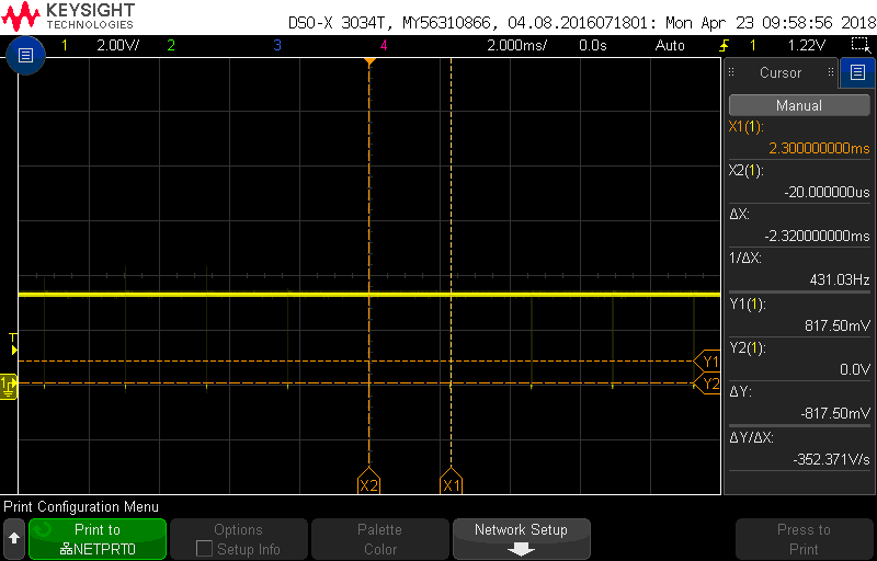
I'm trying to evaluate the VAD function on TLV320AIC3254EVM-K, But I did not get the expected signal on GPIO pin (TP24). With or without voice/music input from IN1, the GPIO pin always output a low state every 2.3ms. 

VAD properties:

INIT_PRD = 1

VAD_TH_DB = 9

VAD_HANG_PRD = 0.5

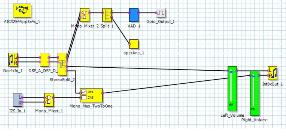
The pfw file as below.

Thank you

  • Hi, Neil,

    Welcome to E2E, Thanks for your interest in our products!.

    The pulse train monitored actually is the expected output when an interrupt is triggered in the miniDSP. It is possible that the interrupt is triggered even without an input signal because the data out from the VAD block is not being detected properly by the GPIO block. Can you please share the process flow?.

    Best Regards,

      -Diego Meléndez López
       Audio Applications Engineer

  • Hi Diego,

    Thanks for your reply.


    Process flow? I'm not sure what you mean.

    I don't know how to attach my pfw file on this forum, but you may refer to the diagram I mentioned previously.
    Below is my test case on EVM.

    1. Generate code form PPS utility then download and run it.
    2. Once the PPS enter a running state, input a sound to IN1(EVM J1)
    3. Then I expect the GPIO pin output a high signal, otherwise, the GPIO pin output a low signal if no sound input.

    What I need is to detect if any sound input from left ADC channel, if no sound input then reduces the left DAC gain after 5 minutes.

    Then, if a sound input again then restore the DAC gain. So, my MCU program can monitor the level of GPIO pin of AIC3254 and do the auto-volume-down function.

    If you could share a reference designed pfw file that will be better.

    Thank you very much,
    Neil
  • Hi, Neil,

    Process flow is the name given to the PurePath Studio block architecture used to configure a certain audio signal processing. For an application like this, you might want to use a different block as a comparator which might be able to provide a direct logic output through the GPIO, different to the VAD which outputs a variable value between 1 and -1. One thing to note is that the way GPIO block is used, when a "1" value is input to GPIO, the output would be the pulse train mentioned before, while a logic 0 is output when a "0" value is input to GPIO block. Unfortunately, right now we don't have an example process flow for an application like this.

    Best Regards,

      -Diego Meléndez López
       Audio Applications Engineer