This thread has been locked.

If you have a related question, please click the "Ask a related question" button in the top right corner. The newly created question will be automatically linked to this question.

CCS/TLV320AIC3254: No LOL/LOR output

Part Number: TLV320AIC3254

Tool/software: Code Composer Studio

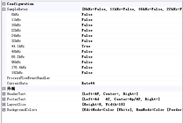
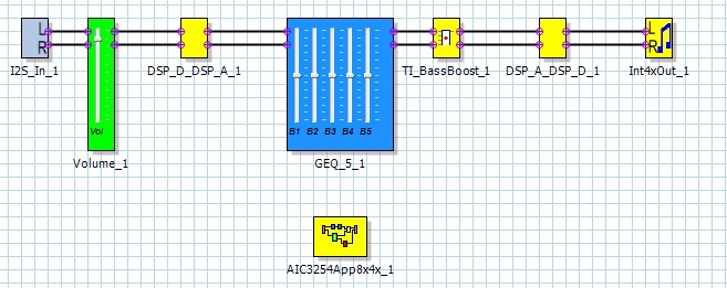
my ctm cinfig tlv320aic3254 like this pic

but the LOL/LOR has no signal out, and I2S has no output.

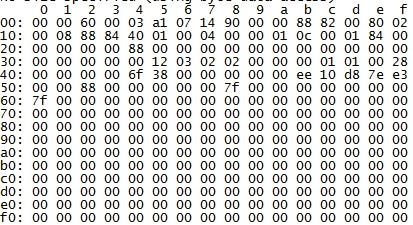
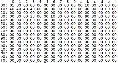
They guess there has something wrong with the config of PLL or power.

Any possible to share the config of the PLL and power and let ctm has some output first.

tlv320aic3254

  • HI, Piero,

    Based on the shared diagram, if the system settings code of PurePath Studio (PPS) is not modified, you should be able to see the an output signal through LOL and LOR outputs. I²S output is not configured on the process flow, so it is not expected to get an output there.

    PLL and power parameters are configured by the Systems Settings code in PPS, and are set correctly by default. Are you using the EVM to test this configuration?. What is the sampling rate used and digital audio source used?. What is the audio source used to provide the I²S input for your test?

    Best Regards,

      -Diego Meléndez López
       Audio Applications Engineer

  • ctm use freescale as the host to connect with tlv320aic3254, use i2s as the input, the sampling rate is 44.1K and MCLK 24M

    current issue is when play audio, there is no signal on WCLK and BCLK.  Also no signal on LOL/LOR.

    Any suggestion?

  • Hi, Piero,

    When using the EVM and external audio source, you need to connect the audio clocks to the header J14 of the Motherboard and set switches 4 and 5 of SW1 to the OFF position. Once this is done, you need also to adjust the PLL coefficients in the systems settings code in PPS to accept the 24MHz MCLK and derive the internal clocks properly. The issue you are describing is weird, WCLK and BCLK should not be stopped during playback.

    Are you trying to use the AIC3254 as Master device? If so, you need also to modify the system settings code to configure the device for this operation mode.

    Best Regards,

      -Diego Meléndez López
       Audio Applications Engineer

  • ctm can only find below setting in PPS

    Would you help for where they can " adjust the PLL coefficients in the systems settings code in PPS to accept the 24MHz MCLK and derive the internal clocks properly"

    Thanks

  • Hi, Piero,

    The System Settings Code I referred before is located in the properties section of the Framework.  Please refer to this wiki entry to find how to change the system settings of the PPS process flow.

    Best Regards,

      -Diego Meléndez López
       Audio Applications Engineer

  • have set the  the PLL coefficients with 2 ways.

    1)

    %%if (%%prop(SampleRate) == 44100 || %%prop(SampleRate) == 48000)

           reg[  0][  5] = 0x91    ; P=1, R=1, J=8
           reg[  0][  6] = 0x08    ; P=1, R=1, J=8
           reg[  0][  7] = 0x00    ; D=0000 (MSB)
           reg[  0][  8] = 0x00    ; D=0000 (LSB)
           reg[  0][  4] = 0x03       ; PLL_clkin = MCLK, codec_clkin = PLL_CLK, PLL on
           reg[  0][ 12] = 0x88   ; MDAC = 8, divider powered on
           reg[  0][ 13] = 0x00   ; DOSR = 128 (MSB)
           reg[  0][ 14] = 0x80   ; DOSR = 128 (LSB)
           reg[  0][ 18] = 0x02   ; NADC = 2, divider powered off
           reg[  0][ 19] = 0x88   ; MADC = 8, divider powered on
           reg[  0][ 20] = 0x80   ; AOSR = 128
           reg[  0][ 11] = 0x82   ; NDAC = 2, divider powered on

           %%endif

    2)set register with I2C as the page0 and page1 as below

    But still can not get the clk out.

    Pls suggest.

  • Hi, Piero,

    Apart from the PLL clock configuration, in order to configure the device in master mode, you need to configure BCLK and WCLK as outputs, as well as enable and configure  the BCLK divider. For this, you need to configure register Page 0 / Register 27 and Register 30.

    The PLL settings you shared seems as the default ones for the EVM, which are fine when a MCLK of 12.288MHz is used. if 12MHz clock is used, coefficient D of the PLL should be 1920.

    Best Regards,

      -Diego Meléndez López
       Audio Applications Engineer

  • OK,See the clk out after set register 30.

    For coefficient D, I didn't find how to calculate the value on the slaa408a.pdf 

    Currently the MCLK is 24M, what's the value we should set for coefficient D?

  • Hi, Piero,

    Thanks for the feedback. If the input MCLK is 24MHz, both coefficients J and D should be updated. J should be set to 4 and D should be set to 960. the information about the PLL coefficient calculation is available in section 2.7.1 of the Applications Reference Guide. Basically you need to write a hex 960 (0x03C0)  value into registers 4 and 5 to configure coefficient D.

    Best Regards,

      -Diego Meléndez López
       Audio Applications Engineer