This thread has been locked.

If you have a related question, please click the "Ask a related question" button in the top right corner. The newly created question will be automatically linked to this question.

PCM5102A: decoupling 3.3 V power supply terminals

Part Number: PCM5102A
Other Parts Discussed in Thread: PCM2706C, PCM5102, PCM2706, ISO7240C, LP2992

Hello,

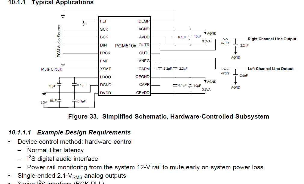
Having issue with your Application and Implementation on page 26 of the datasheet with part number PCM5102APWR.

Here is the flow:

[ PCM2706CPJTR] > i2s > [PCM5102APWR] > {AMP OUT}

THAT is PCM2706C USB to PCM5102A DAC  to Amplifier Speaker.

I have it setup for PCM5102a PLL Operation 3.3v on a breadboard, clean 3.3v power supply.

Also the XSMT PIN 17 wired to AVDD PIN 8 on the 'Breadboard', per the TI datasheet recommendations. THIS IS THE ONLY DEVIATION.

I have swap out the PCM5102A DAC with another DAC,the ES9023, and the setup works fine!

HOWEVER the TI PCM5102A IC is module not working. I have replace the IC Module with another PCM5102A chip, but same result.

QUESTION:

1. Where do I wire XSMT PIN 17, to AVDD and or DVDD!

2. What is the I2S hardware configuration for optimal high-resolution performance!

3. What is the best TI I2S hardware configuration recommended!

Note I have review the wiring to your Application and Implementation on page 26 of the datasheet to my breadboard wiring using the same BOM and wiring. Not getting any signal output!

I have replace the IC since we have several PCM5102 IC module made up for bread-boarding.

Regards

  • Kindly see the schematic for reference, thank you.
  • Hi Neil,

    Breadboarding complex configurations can be problematic as simple errors may not be easily detected.  Firstly, I would confirm that all of the required additional circuitry is connected correctly, specifically charge pump cap between CAPM and CAPP, the stability capacitors on LDOO and VNEG, as well as the state of the configuration pins (FMT, FLT, and DEMP).  Assuming those are correct, and XSMT is tied high (note muted) by being connected to any 3.3V supply, we should confirm that the I2S data is valid.  If FMT is grounded, the device is expecting standard I2S data.

    Note that in 3-wire mode, only a select number of rates are allowed.  Table 11 lists these.

    In addition, if you are using 3 wire mode on a breadboard, I recommend you GND SCK to ensure that now digital feedthrough on the board is causing the PLL auto-detect to think there is a clock on the line.

    I think checking these configurations should fix the issues.

    Thanks!

    Paul

  • Hello,

    I have double check the wiring to the TI design and wiring to our breadboard, and have same.

    I followed the outline direction and set all wiring to follow the guided direction.

    However not getting the I2S signal out!

    Note I swap out the PCM5102A with another DAC; and it and works!

    However the PCM5102A has no I2S SIGNAL!

    Not sure what else to check!!! 

    ....Just pop the IC add another, same....no signal out.

    Neil Henry

  • What is the frequency of the I2S sample rate and bit clock frequency you are using? Can you confirm the voltage on VNEG and LDOO when the I2S signal is being applied?
  • Hello Paul,

    We are using the PCM2706C USB I2S on the input. It had has bit clock frequency of 12MHZ and the I2S sample rate is 48KHZ. We are confirming the voltage on VNEG and LDOO.

    What must be the voltage on VNEG and LDOO when the I2S signal is being applied?

    We have supply at 3.3v AVDD, CPVDD, and DVDD.

    Our QC Engineers ask, "How can we know if the IC is operable before assembly on the circuit board i.e. breadboard?"

    What is the TI Quality Control procedure for the IC? They want to test the TI IC prior to production, need your help here, thanks.

    Best Regards,

    Neil Henry

  • If the I2S signal is valid the device should enable the low power LDO (LDOO) which should measure 1.8V, and the charge pump (VNEG) which should be -3.3V.

    These components are all tested before being sold through our distributors.
  • Paul,

    Thanks for the update.

    BASELINE:
    BEFORE I2S Signal Test:

    CPVDD = +3.55V
    DVDD = +3.42V
    AVDD = +3.10V
    LDOO = +3.42V
    VNEG = +3.25V

    BASELINE:
    AFTER/DURING I2S Signal Test APPLIED:

    LDOO = 0.35V [I2S signal applied]
    VNEG = 0.38V

    These measurements don't add up.

    Not sure what this means! Before shows +3.5V but during I2S signal test it goes to 0.35v. SOS!

    Neil Henry
  • Hi Neil,

    Please verify that you have nothing connected to the LDOO pin besides the capacitor - this is an LDO output, not input. Also verify that nothing is connected to VNEG except the capacitor. I would also meticulously verify the ground pins are connected.
  • Hi Paul,

    Our lead engineer has verified that nothing is connected to LDOO and VNEG besides the suggested capacitor per the datasheet schematic.

    Another engineer took on the project, and wired it on a new breadboard with all new parts and IC.

    However not getting I2S signal to PCM5102A DAC.

    FLOW:  USB TI PCM2706C <> I2S <> DAC TI PCM5102A <> AMP <> SPEAKER

    WE  test the flow {USB PCM2706C <> I2S <> DAC ESS ES9023P <> AMP <> SPEAKER} this works GREAT.

    However our project goal is to use the chipset - PCM5102A.

    Not sure what else to do....just baffled!

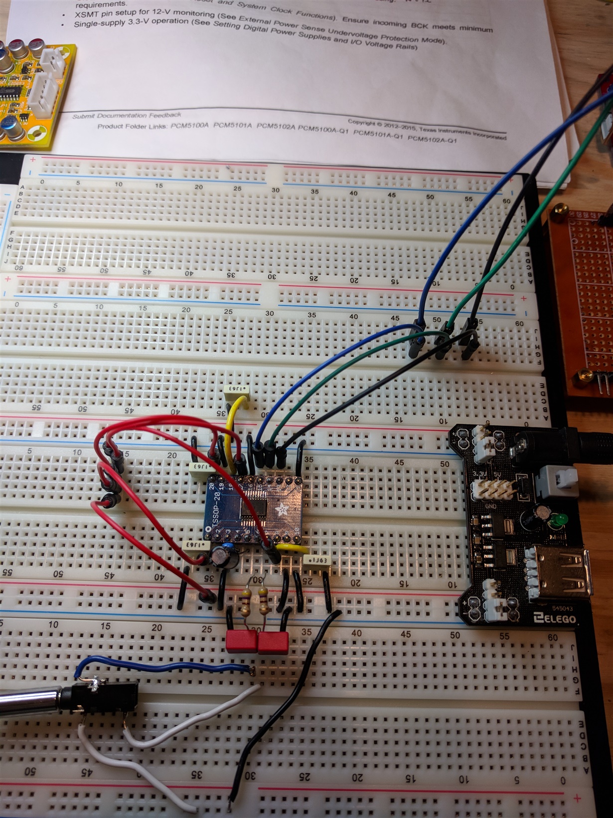
  • Do you mind posting an image of the setup? Can you confirm what you have XSMT connected to?
  • Hi Paul,

    I have XSMT wired to +3.3V. However I have rewired the circuit.

    Note now the results are that when I connect the circuit to I2S via the USB PCM2706C all pins goes to zero volts. I have narrow the problem to the I2S connectivity @ the USB input via the PCM2706C! But when I connect another DAC board it works!

    However all pins are LIVE prior to the I2S connectivity!

    What must the I2S pin measure at when supply power at 3.3V PINS 13, 14 and 15! Sorry my question mark at keyboard not working at the R&D Lab.

    Neil Hnery

    IRAD

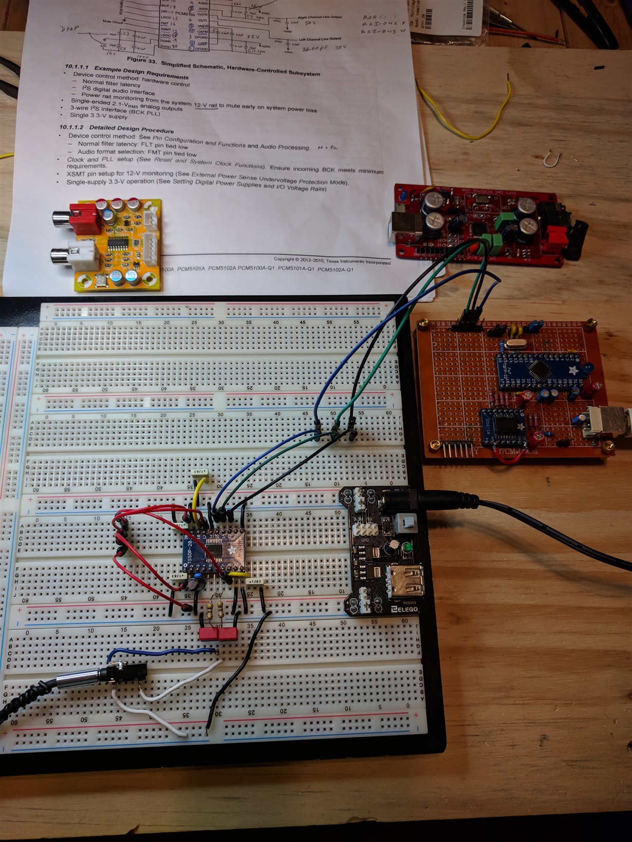
  • Here is the circuit. Hope helps!

  • Please note SCK Pin 12 connect to GND; normally connects for PLL operation. On the pics I had took it out, to try PCM audio operation. However same result I2S goes inoperable not live when I add I2S connectivity to the USB circuit. The Yellow ES9023P board on top left works with the two USB PCM2706c board on the right of the breadboard.

    Not sure why it goes to "0V" when I connect the I2S input to the circuit.

    Neil Henry
  • To be clear, the PCM2706 is providing the I2S signal and is the I2S master, in that it generates SCK,BCK,LRCK, and SDIN? Have you connected an oscilloscope to verify the I2S lines are formatted correctly? (based on the FMT pin). What is the I2S frequency?

    Thanks!
  • The PCM2706C is the master and PCM5102A setup for PLL operation.

    We have made progress. When we took off the PCM5102A IC and replace it with another, the system came up!

    Strangely we have now tested 10 TI PCM5102A IC utilizing the board that works. Found six not working using that working board as the test bed frame of reference.

    What is the process for replacing these TI PCM5102A IC not working?

    IRAD

    Neil Henry

  • Hi Neil,

    I am not seeing any ground connection between the PCM270x board and the PCM5102A. Can you configure the PCM2706 for a lower speed? I wonder if the long cabling/breadboard could be adding a lot of capacitance and inductance to the I2S lines. 3MHz is still pretty fast for a breadboard.

    Any device returns would be coordinated from the distributor you used.

    Thanks!
  • Hi Paul,

    Point duly noted.
    On the USB PCM270x board, it is wired for just I2S interface; and another ISO7240C digital isolator interface with I2S, 3.3v and GND.

    I have it wired as you suggested after resolving the defective IC out of the equation.

    I have since added 22ohm on the I2S interface to minimize signal reflection!

    The circuit works GREAT!

    My next step is to add the low-noise voltage regulator LP2992 and or better! Any thoughts here?

    Note the ICs I had purchase from your Web Store.

    Thank you

    Neil Henry
    IRAD
  • Great to hear! I guess a picture tells a thousand words!

    I do not have any specific tips about the LP2992, though it might be useful to post your schematic on the power forum for review.

    Good luck,
    Paul