This thread has been locked.

If you have a related question, please click the "Ask a related question" button in the top right corner. The newly created question will be automatically linked to this question.

PCM1862: Problems configuring through SPI

Part Number: PCM1862
Other Parts Discussed in Thread: PCM1865,

REgisters setup through SPI interface fails.

We are using a PCM1865 IC , we want to configure come registers through the SPI interface. (Our uC as SPI Master and the PCM as SPI Slave)

We are using the initial sequence showed in the atttached file

After that we want to validate that effectively we have configured what we want. So we are trying to read the Register6 several times. The point is that we see nothing in the MISO line. So it seems that we cannot read (and therefore probably we are not writing properly either)


As HW setup we are using the next pinout configuration.
pin 26 attached to 3.3V to choose SPI interface;
pin 25 CS
pin 24 CLOCK
pin 23 MOSI
pin 22 MISO

The SPI Clock signal is 500KHz, we are using CPOL = 0 and CPH = 1 (i.e fetching data in the falling clock edge)

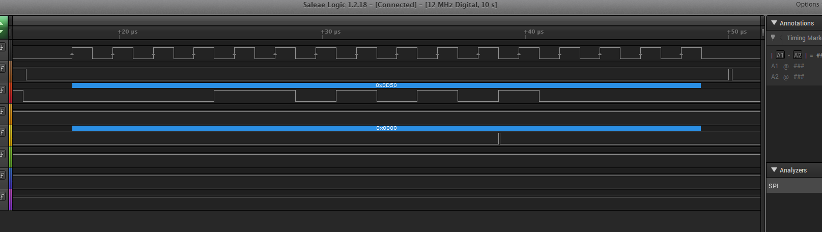
Here I insert some relevant captures of our frames . Maybe we are using a bad timing or maybe we need some write operation before being able of reading anything.

Writing register 6

REading register 0x6 , we expected to read the same 0x50 we inserted previouly.

  • Hi, Alberto,

    Welcome to E2E, Thanks for your interest in our products!.

    This is not a common issue, the device should be capable of communicating via SPI. Can you please verify the device behavior to see if the part is actually being configured? like changing the analog gain of the ADC while monitoring the output.

    Is it possible to try using an I2C interface to verify the device is working correctly?.

    Best Regards,

      -Diego Meléndez López
       Audio Applications Engineer

  • Hi Diego,

    thanks for the reply, finally I've managed to read properly the registers. 

    After the bootup I read certain registers and effectively I read the default value indicated in the Data Sheet. Eg:

    Add 6 -> 0x41

    The point now is that it seems that I cannot write such registers. 

    My code is as simple as:

      PCM1862_Read(6, 0);
      delay(20); //ms
      PCM1862_Write(0, 0);
      delay(20); //ms
      PCM1862_Write(6, 0x50);
      delay(20); //ms
      PCM1862_Read(6, 0);
      delay(20); //ms

    So I expected to read the 0x50 value, but I always read the default 0x41. So I'm I missing something here? Do I have to enable the write operations somehow?

    Tofurther information I show here my simple library functions

    void PCM1862_Write(uint8_t address, uint8_t value) {
      // take the SS pin low to select the chip:
      digitalWrite(slaveSelectPin, LOW);
      //  send in the address and value via SPI:
      SPI.transfer((address << 0));
      SPI.transfer(value);
      // take the SS pin high to de-select the chip:
      digitalWrite(slaveSelectPin, HIGH);
     
    }

    void PCM1862_Read(uint8_t address, uint8_t value) {
      uint32_t readVal;

      // take the SS pin low to select the chip:
      digitalWrite(slaveSelectPin, LOW);
      //delay(1);
      //  send in the address and value via SPI:
      SPI.transfer((address << 1) | 1);
      readVal = SPI.transfer(value);
      // take the SS pin high to de-select the chip:

      Serial.print("Read Value: add ");
      Serial.print(address, DEC);
      Serial.print(" = 0x");
      Serial.print(readVal, HEX);
      Serial.print("\n");
     
      //delay(1);
      digitalWrite(slaveSelectPin, HIGH);
    }