A related question is a question created from another question. When the related question is created, it will be automatically linked to the original question.
If you have a related question, please click the "Ask a related question" button in the top right corner. The newly created question will be automatically linked to this question.
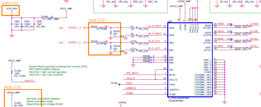
How much value capacitors did you try? Basically the DC block capacitors on the input only changes the HPF bandwidth, please find more info about this in the section 7.3.2 in the datasheet. So for the lower frequency input signal, the output amplitude changes wih the input capacitors.
Please don't use the voltage divideded resitors network(T9101~R9104) on the input, because it could introduce mismatch on the differential input and then it's very easy to cause pop noise is in single-ended input mode during power-up.
Hi AJ,
Thank you for your update. Is the pop noise within the acceptable range for your solution please? In another word, the pop noise issue and the gain issue can be resolved at the same time, right? Actually we don't recommend users to changing the gain by adapting the input circuit, because the any imbalance on the differential input could be enlarged on the output and cause noise on the speaker, especially this is a single-ended input application. Is it possible to decrease the input signal amplitude?
Best regards,
Shawn Zheng
Dear Shawn.
Thanks for your reply.
Yes. pop noise issue and the gain issue can be resolved right now.
I can understand your explanation. However, the amplitude of the input signal cannot be changed.
Therefore, We chose to change the input circuit.
If the music test is normal, will there be other risks? Thanks for kindly help~
HI AJ,
Thanks for your reply. The biggest risk is still the pop noise. The resistor/capacitor tolerence could also cause the imbalance on the differential mode. You need to do the test on many boards to make sure the issues can be fixed on all of them.
Best regards,
Shawn Zheng
Dear Shawn
Good day.
After we remove the R9102 / R9104 and keep the R9101 / R9103 and change the C7 / C770 to 1.5nF, verify that the 60 board is fine.
We need to know Is the current practice the best solution or have other better solutions can provide to us? Thanks for kindly help.~
Hi AJ, Thanks for your update. As I explained sbove, the best solution is to shrink the input signal amplitude. If resistor divider circuit has to be used here, you could select the appropriate resistors and capacitors for the input circuit, as soon as the pop noise is accepatable. Best regards, Shawn Zheng