This thread has been locked.

If you have a related question, please click the "Ask a related question" button in the top right corner. The newly created question will be automatically linked to this question.

LM4838: LM4838 amp out have click noise

Part Number: LM4838
Other Parts Discussed in Thread: LP2987, LM1117, LM4940, LM4952, LM4950, LP2988

Hi Sir,

Our customer used the LM4838 on product, but have Fail Rate=12/10000=0.12% click noise issue.

Please see the attached file, the fail PCB LM4838 R&L output not stable.and Bypass pin also not stable.

Currently customer is used the 1uF Ceramic capacitors on Pin22, 

Is it caused by this factor?

Is must use the "Tantalum Capacitor" on Pin22? 

If customer want to use the ceramic capacitors on pin22, what value for suggest? or do not use ceramic capacitors? 

LM4838.pdf

  • HI Sir,

    update the package is TSSOP. Pin22 is Bypass function.

    Hugo
  • Hi Hugo,

    The bypass pin should be selected following the same recommendations as a power supply decoupling capacitor. So tantalum is best.
    You could try to change the ceramic cap on bypass pin for tantalum and evaluate performance.

    Best regards,
    -Ivan Salazar
    Applications Engineer - Low Power Audio & Actuators
  • what kind of the different tantalum cap and ceramic cap for BYPASS PIN ?
  • Derek,

    You can try with the suggestions from the data sheet:
    Tantalum Capacitor 1.0µF 16V 10%

    Best regards,
    -Ivan Salazar
    Applications Engineer - Low Power Audio & Actuators
  • Tantalum capacitors are rarely used nowadays.
    What else can be improved?
  • Derek, Hugo,

    What capacitor are you using on bypass pin? Could you share the part number?
    Perhaps trying electrolytic cap. The recommendation from the data sheet states that ceramic caps should not be used as they could cause oscillations.

    Best regards,
    -Ivan Salazar
    Applications Engineer - Low Power Audio & Actuators
  • Dear Derek,

    please provide the samsung PN complete, Thanks.

    Hi Sir,

    our customer is used samsung MLCC.

    SAMSUNG MLCC_200911全系列.pdf

  • SAMSUNG PN: CL05A105KP5NNNC
  • Hi Ivan,

    Can provide reasons why it happened?
    Is there any reason for this phenomenon?

    Because of the capacitor material?

  • Hi Ivan,

    What is the oscillation?

    How to distinguish the oscillation on the waveform?
  • Derek,

    There is an internal resistor divider for the bypass mid-supply voltage. Perhaps the ceramic capacitor along with the internal resistors are resonating and causing oscillation.
    You can see the oscillation on your captures (from the first post). The capture from bypass pin is not stable, and if the mid-supply reference voltage is not stable the output will also be unstable.

    Best regards,
    -Ivan Salazar
    Applications Engineer - Low Power Audio & Actuators
  • Hi Sir,

    Summary customer Derek question as below , customer is sell over 3 year  product to market,

    need check this output Triangle wave root cause.

    Q1 Can provide reasons why it happened? 

    Q2 Is there any reason for this phenomenon?

    Q3 What is the oscillation? could you please share the waveform or data to explanation?

    Q4 How to distinguish the oscillation on the waveform?

    Q5 Tantalum capacitors are rarely used nowadays. What else can be improved? why TI not recommand use the Ceramic?  could you please share the waveform or data to explanation?

    Hugo

  • Hi Sir,

    We are see the Old LDO have similar issue, need high ESR CERAMIC or TANTALUM.
    Does LM4838 oscillation is similar issue?

    LDO LP2987/LM1117/TPS76933DBV
    Audio amp LM4952/LM4950/LM4940

    TPS76933DBV Ceramic Capacitors Replace Tantalum Capacitors in LDOs
    www.ti.com/.../slva214a.pdf

    Hugo
  • Hi Hugo,

    Yes, this might be similar behavior you're seeing in LM4838.

    Best regards,
    -Ivan Salazar
    Applications Engineer - Low Power Audio & Actuators

  • Hi Ivan,

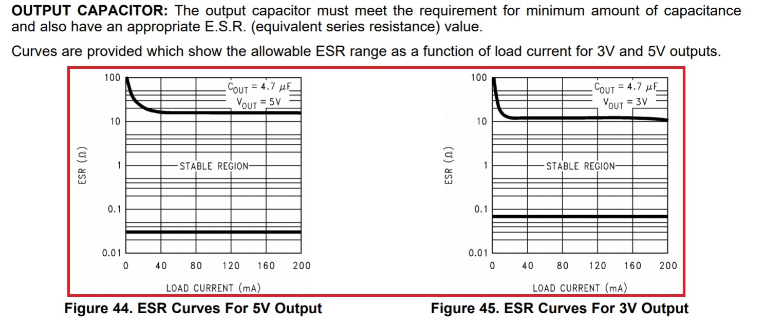
    Is there a recommended ESR range?

  • Derek,

    Documentation of this device is very limited. ESR would need to be high to keep the product of capacitance and resistance high. Some possible workarounds to replace the tantalum capacitor would be to add a series surface mounted resistor in series with the bypass capacitor to compensate the ESR difference. The second option is to use an electrolytic capacitor that is somewhat similar in terms of ESR to the tantalum.
    Another important thing is to have a good decoupling at supply pins (VDD) by placing 10uF and 0.1uF capacitors as close as possible to the device. Decoupling capacitor on bypass pin should also be placed as close as possible to the device.

    Best regards,
    -Ivan Salazar
    Applications Engineer - Low Power Audio & Actuators
  • Ivan,

    How do we try the ESR values of our experiments?


    No ESR value range.

  • Hi Ivan 

    May we know the LM4838 ESR range ?

    Below is LP2988's datasheet ,it have recommend ESR range  

  • Hi Ivan

    Sorry!! this end customer is from Japan ,so can't use tantalum capacitor

    1. End customer would like to know how to select ceramic capacitor ,what's the frequency and ESR need to confirm ?

    2. Or you think this is layout issue need to review again ?

    3. When we remount the MLCC cap ,the issue will disappear 

    Please kindly help to support this case ,we have to explain to our customer 

  • Kai,

    I would like to test different components but unfortunately I don't have access to any evaluation board for this device.
    Remounting MLCC cap fixes the issue all times? Perhaps this could be a contact issue when soldering?

    Best regards,
    -Ivan Salazar
    Applications Engineer - Low Power Audio & Actuators
  • Hi Ivan

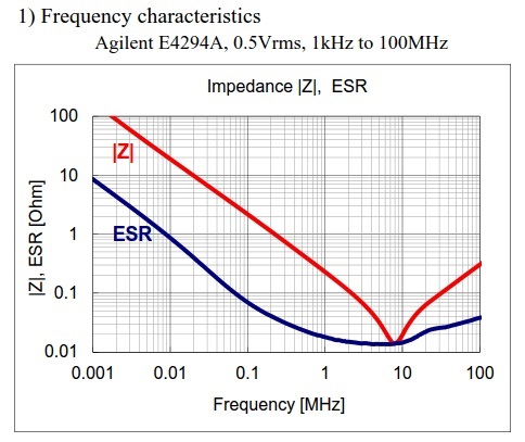
    So far we check the ESR value for failure condition ,the value is 0.05ohm at 100KHz 

    If the value 0.1ohm at 100KHz ,it will not have this failure condition

    If you would like to verify LM4838 ,we can provide one board to you 

    Our end customer would like to know how to select the cap ,due to the latest tantalum cap have low ESR version 

  • Ivan,

    The current experimental results show that the abnormal state is mainly followed by the capacitance.

    We don't understand what is the MLCC's characteristics that affect the abnormal state.

    We also measured the normal and abnormal capacitance values and ESR values at 1KHz, there is no obvious difference, the larger difference is at 100KHz.
  • Derek, Kai,

    Based on the tests results you've shared there are a couple more things I think we could try:
    Ceramic capacitors tend to have considerable capacitance variation over DC Bias and also Temperature. If high temp caused the symptom perhaps the capacitance variation over temperature is causing it. What would be high temperature?
    Small form factor MLCC caps usually have the highest variations, from the beginning of this discussion I recall they were using CL05A105KP5NNNC.
    Some things I would try are to use X7R instead of X5R, perhaps the temp tolerance could benefit the performance. Also try with a bigger form factor cap.
    In addition if capacitor is vibrating or even emitting some noise, perhaps trying a C0G cap could help to identify if this could be causing the problem.

    Best regards,
    -Ivan Salazar
    Applications Engineer - Low Power Audio & Actuators
  • Ivan,

    1.
    We have experimented with low ESR capacitors and the abnormal state has not appeared.
    We feel that there is no direct relationship with the level of ESR.
    What other characteristics may affect the output of the AMP IC?

    2.
    When testing, we use 60 degrees at high temperature,
    but the actual application will be in the general temperature,
    the temperature coefficient may be less important.
  • Derek,

    As I cannot get any further details about the device internal bias circuitry or how it works I cannot tell what is the one thing that affects its stability. We only have what's on the data sheet.
    Other than ESR I could only think of the variation in capacitance, so reduced tolerance/variation caps would be the way to go; this was commented in the previous post mentioning the DC bias and temperature variations.
    This is a fairly old device so there is little information we can get to know about it.

    Best regards,
    -Ivan Salazar
    Applications Engineer - Low Power Audio & Actuators
  • Ivan,

    To understanding.

    Let's change direction and want to know what the main function of BYPASS PIN is for AMP IC?

    Assuming that the BYPASS PIN is disturbed, what happens to the IC itself?
  • Derek,

    Bypass pin is connected to an internal voltage divider, that set the DC bias for the device common-mode voltage; usually this voltage is around VDD/2.
    If the bypass pins is disturbed, then the DC bias of the device will be affected in the same way. As bypass is the center DC bias, the output will be directly affected by that.

    Best regards,
    -Ivan Salazar
    Applications Engineer - Low Power Audio & Actuators
  • Ivan,

    How do we describe the current anomaly caused by the interference of the BYPSS PIN ?

    How do we link the anomaly to the BYPASS PIN ?
  • Derek,

    How do we describe the current anomaly caused by the interference of the BYPSS PIN ?
    - Bypass pin has the common-mode reference (DC bias) of the device, so if something affects bypass then it affects the output as well, since the DC bias is the voltage at what the signals are centered.

    How do we link the anomaly to the BYPASS PIN ?
    - Captures of the bypass pin signal show variations of the voltage over time. From testing, it seems that changing the capacitor on bypass pin makes the signal stable. Although it is uncertain what is the exact parameter of the capacitor that is causing this behavior.

    Best regards,
    -Ivan Salazar
    Applications Engineer - Low Power Audio & Actuators
  • Ivan,

    Why is this happening actually, except for ESR and temperature coefficient, there is no other idea?