This thread has been locked.

If you have a related question, please click the "Ask a related question" button in the top right corner. The newly created question will be automatically linked to this question.

DRV135: High Frequency (11.4 KHz) noise issue

Part Number: DRV135
Other Parts Discussed in Thread: MAX660, TPS563209, PCM1681

We are using DRV135 to generate balanced audio output in one of audio application. But on the output we are getting high frequency tone (11.4 KHz precisely) when there is no audio present.

We have also added two schottky diodes on each output to protect the unit from phantom power. 

This high frequency tone is always there. We tried different value capacitors to filter out the tone but it is not plummeting at all.

  • Hi Dhaivat,

    Could you provide your schematic? It is difficult to propose a cause for this without seeing your application. 

  • Currently we haven't placed 0.68uF capacitor.

    DRV135 section:

  • Oops, remove these terrible 680nF caps (C223 and C224) from the outputs !! They erode the phase margin and make the DRV135 oscillate.

    Kai

  • We already removed it. But when we did that we are getting so much humming noise.
  • We have multiple channels like this. We have removed 680nF from all channel but we are getting so much humming noise. It looks like common mode noise. Is there any way to reduce this humming?
  • Hi Dhaviat,

    where is the hum comming from? Do you have any hum loops?

    Can you show your wiring scheme?

    Kai
  • Hum is coming from XLR output. I don't think we have any hum loops.

  • Hi Dhaivat,

    If the hum is only present when connected to another piece of equipment, it's possible that you are seeing a ground loop formed with external equipment, given that chassis ground and analog ground are tied together. 

    If the hum is always present, regardless of external connections, then I suspect you're seeing noise from your DC/DC converters appearing at the output of the DRV135. It's possible that this coupling is happening through the power supply connections of the DRV135, but given your filtering scheme and the PSRR of the DRV itself, I think it's more likely that this signal is coupling upstream of the DRV - hence why the filtering capacitor on the DRV output helps improve the output hum.  

    If this hum signal is strong enough to be visible on an oscilloscope, I'd check its level at the DRV135 output, then at its input. This would start to point us in a direction for its source. 

  • Hi Dhaivat,

    additionally to what Alexander says, can you tell us, what you mean by "hum"? Is it mains hum (50Hz)? Or is it rectifier hum (100Hz)? Or is it the switching frequency of the DC/DC-switchers you can hear?

    Divide and conquer! Let's make a simple test: Disconnect everything from the outputs of all DRV135 circuits. Disconnect the inputs of all DRV135 circuits and connect them directly to signal ground. Now, no hum should be heard.

    If, however, hum is hearable, then it probably comes via the supply pins. Temporarily connect 100µ electrolytics in parallel to C33 and C63 and put 100R resistors into the supply lines so that a RC low pass filter is formed in each supply. If the hum is switching noise from the DC/DC-switcher which enters the DRV135 via the supply pins, the hum must become much quieter now. In this case the DC/DC-switcher need additional filtering.

    Please perform this test and report the results.

    Kai

  • Hello Kai,

    I disconnected the input of DRV135 and tied it to ground. and check audio on XLR. I am getting high frequency noise (approximately 11.4 kHz). I made the changes as you instructed but I am seeing no significant change and also it is dropping the voltage level from 5Vdc to 1.7Vdc which ultimately attenuating the audio output.

    Regards,
    Dhaivat Master
  • Hi Dhaivat,

    the DRV135 has a supply current of about 5mA, if no relevant load is connected to the output. This should give a voltage drop of only 0.5V across the 100R resistor. The recommended RC-low pass filter should only be used for ONE DRV135, not all togther.

    Can you show scope plots of the +5V and -5V supplies? Is there any noise on the supplies?

    Kai
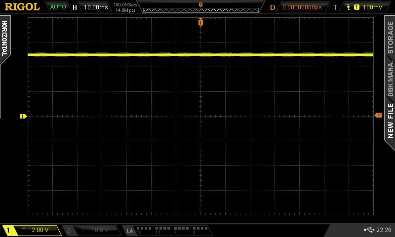
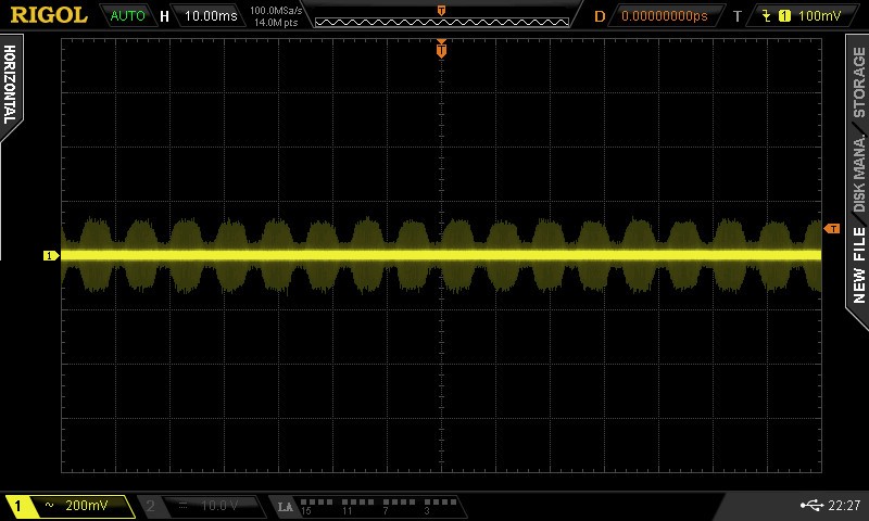
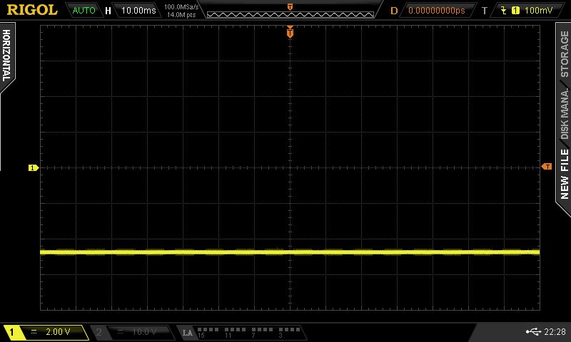
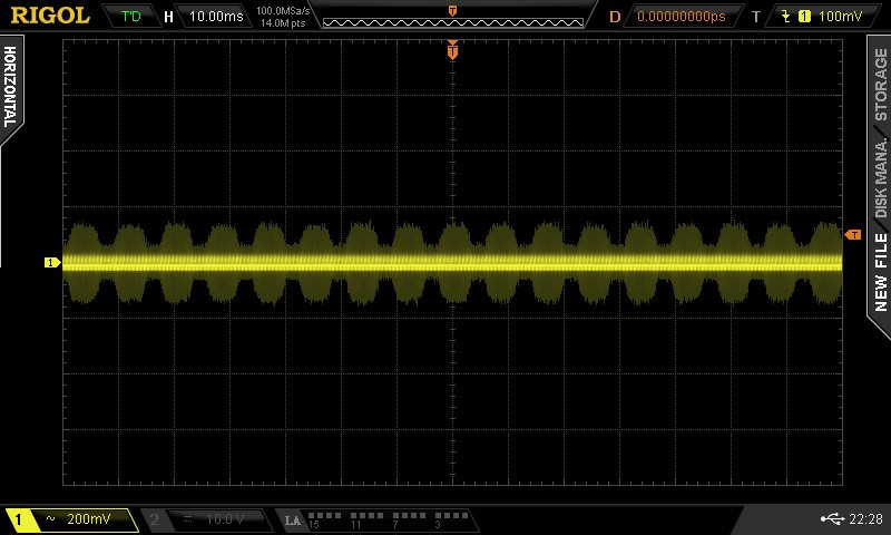
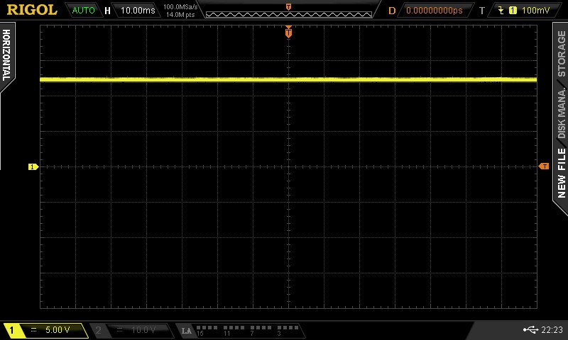
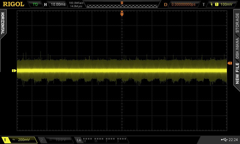
  • Here are the scope plots of +5V, -5V and 12V power supply.

    1. +5 VDC 

    2. +5 V noise (Coupling set to AC on Oscilloscope).

    3. -5 VDC


    4. -5 V noise (Coupling set to AC on Oscilloscope).

    5. +12 VDC Power Supply

    6. +12 VDC Supply noise (Coupling set to AC on Oscilloscope).

  • Hi Dhaivat,

    Oops, that's huge noise! You should add low pass filtering. Pi-filters can help: Take a 10µH choke and two 100µF caps to form a pi. Add a 1R resistor in series to the choke to dampen any resonance and 470n caps (foil, X7R) in parallel to the 100µ caps. Put this pi-filter directly to the input and to the output of every DC/DC-switcher. Of course, other components are also possible, if you don't want to use big electrolytics.

    What DC/DC-switchers are you using?

    Kai
  • To convert 12V dc to +5V dc we have used TPS563209DDC
    and to convert +5V dc to -5V dc we have used MAX660MX.
  • Hi Dhaivat,

    the MAX660 switches at arround 10kHz... Could this be your 11.4kHz noise??

    The switching frequency of MAX660 can be changed from 10kHz to 80kHz. Have you checked this? Does this make a difference?

    The +5V supply is generated from the +12V by the help of TPS563209. This is a 3A switcher which makes a lot of noise. Do you need so much current for the DRV135?

    Kai
  • Hello Kai,

    We haven't checked the noise by changing the MAX660 frequency. We will try these changes too.

    Actually, we have multiple DRV135s and it is also providing supply to DSP and PCM1681.

    Dhaivat
  • Hello Kai,

    The high frequency noise of 11.4kHz goes away when we set MAX660 to 80kHz frequency. It was the switching noise coming from the output.
    But still we can hear hum which I think can be eliminated by putting pi-filter on output of DC-DC converters.

    Dhaivat
  • Very good!

    Come back if you need any help with the filtering. :-)

    Kai
  • Hello Kai,

    Can we add below shown filter circuit at the output of the DCDC converter for +5AVDD and -5AVDD of DRV135?

    Please let us know if you any other better solution of filtering for +/- 5 V supply.

    Dhaivat

  • One more thing,

    Also for high frequency noise at the XLR output, can we add LC low pass filter at the output of the DRV135 as shown in figure below to remove high frequency noise?

    Can you please suggest us the value of LC for audio range? Can we use ferrite bead or resistor in place of inductor?

    Dhaivat

  • Hi Dhaivat,

    I would replace FB2, FB3 and L14 by 10µH chokes with very high resonance frequency. Put also a resistance in series to each 10µH choke to dampen the resonance. The sum of this resistance and the ESR of 10µH choke should make about 1R.

    The filtering shown in the other post will not solve the issue. This filter decreases the interference which enters the circuit via the output terminals. But your problem is the noise coming from the supply lines, not from the output terminals.

    Kai