This thread has been locked.

If you have a related question, please click the "Ask a related question" button in the top right corner. The newly created question will be automatically linked to this question.

TLV320AIC3109-Q1: Clocking from I2S (external BLCK = 256 kHz)

Part Number: TLV320AIC3109-Q1


My customer want to clock the audio codec from external I2S bus. There are only 256 kHz BLCK has present.
They connect external BCLK signal to BCLK pin and configure it as required for 48 kHz audio. But this configuration don't work.

There are no limits for BLCK frequency provided in datasheet. At the same time MCLK limits at 512 kHz minimum.

The device can accept an MCLK input from 512 kHz to 50 MHz that can then be passed through either a
programmable divider or a PLL to get the proper internal audio master clock required by the device. 
The BCLK input can also be used to generate the internal audio master clock.

Can you clarify limits of BCLK?

It's possible to clock the codec from 256 kHz?

  • Vladimir, 

    Something doesn't add up.   If your customer's BCLK is 256khz,  their wclk cannot be 48khz.    

    48khz * word length * #of channels = Bclk.  

    the minimum word length is 16,  and for standard I2S its only 2 channels. 

    48000*16*2 = 1.536Mhz.

    please comment. 

    To be clear,  the BCLK can of course be as low as 256, but the PLL cannot accept such a low frequency. 

    In the first case where D=0000,  PLLCLK_IN/P must be greater than 2 Mhz.   which means that at 48khz, your word length should be greater, or you need to use pad bits. 

    best regards, 

    -Steve wilson

  • Hello Steve,

    I discussed the issue with the customer.  There are some additional details.

    Customer want to connect our codec with Cinterion modem EHS5.

    The modem use DAI/PCM digital audio interface. Characteristics has fixed by manufacturer and described on page 30 in datasheet https://ptelectronics.ru/wp-content/uploads/cinterion_ehs5_hardware_interface_description.pdf

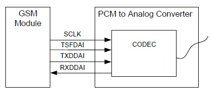
    Schematics is simple, only 4 lines.

    How to configure TLV320AIC3109-Q1 to work with EHS5?

  • Vladimir,

    SCLK -> BCLK
    TSFDAI -> WCLK
    TXDDAI-> SDIN
    RXDDAI-> SDOUT

    Because its 8khz, you will need to setup the Fsref on the AIC3109 for 48khz, but then use page 0 register 2 to divide that down by 6 (for both the ADC and DAC)

    I'd say just use the 16 bit left justified mode. That should do the trick for you.

    best regards,
    -Steve Wilson
  • Hello Vladimir, Steve.

    We use ac-coupled HPOUT & HPCOM in differential mode as output.

    Current settings is:

    300000
    300180
    300000
    3002AA
    300381
    300460
    300500
    300600
    300B00
    300700
    300980
    300E80
    301580
    302B80
    302580
    302600
    303D80
    304195
    306620
    304895
    301980
    30419D
    30489D
    302B00
    300718

    Proper I2C bus working we check by switching MICBIAS voltage.

    Micbias works correctly, but sound doesn't.

    Where is the problem?

    With best regards, 
    Avetis Ter-Avetisyan

  • Avetis,

    For the most part this looks ok, but your last register write assigns the data path for the DAC. this should be done before the DAC/ADC are powered up. This should be one of your first register writes.
    30 07 18

    Also, For your PLL, what is your BLCK frequency? From the look of it the BCLk is 256khz. If this is the case, this doesn't meet the input requirements of the PLL. This needs to be at least 512khz.

    best regards,
    -Steve Wilson