This thread has been locked.

If you have a related question, please click the "Ask a related question" button in the top right corner. The newly created question will be automatically linked to this question.

TLV320AIC3204: Connecting to Sierra Wireless Modem via PCM

Part Number: TLV320AIC3204

Hi,

We've selected your TLV320AIC3204 Codec for use with a modem from Sierra Wireless and i'm having a bit of trouble configuring it to talk to the modem correctly.

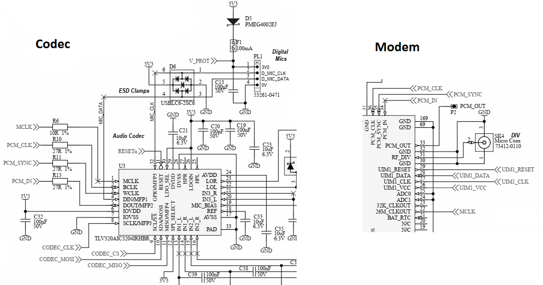
Our system is as follows: 

Host microcontroller to setup the codec via SPI at 3.3V, MCLK is fed from the Modem which has a 26MHz CLKOUT pin. BCLK is connected to the modem PCM_CLK, WCLK to PCM_SYNC and DOUT to PCM_IN on the modem.

We think we've already made one mistake with the design as the Modem operates at 1.8V for it's general GPIO but makes no mention of voltage levels for PCM and our IOVDD on the codec is pulled up to 3.3V to interface with the microcontroller. It would be appreciated if you could confirm that the PCM levels should be at IOVDD level before we make any changes or adjustments

Secondly I've had mixed results configuring the codec, under some circumstances i'm able to ring the modem and hear nothing but silence, but under others i'm able to hear a lot of white noise.

Below is our startup configuration which results in white noise when calling the modem. If you have any suggestions that would be most appreciated.

Processor_Codec_WriteRegister(0x00, 0x00); // Page0
Processor_Codec_WriteRegister(0x01, 0x01);

Processor_Codec_WriteRegister(0x12, 0x81); // Set NADC to 1
Processor_Codec_WriteRegister(0x13, 0x82); // Set MADC to 2
Processor_Codec_WriteRegister(0x14, 0x80); // Set AOSR to 128

Processor_Codec_WriteRegister(0x3D, 0x01); // Select ADC PRB_R1
  
Processor_Codec_WriteRegister(0x00, 0x01); // Page 1
Processor_Codec_WriteRegister(0x01, 0x08); // Turn off weak LDO
Processor_Codec_WriteRegister(0x02, 0x01); // Turn on LDO
Processor_Codec_WriteRegister(0x0A, 0x7B); // Set Vcm to 0.75V
Processor_Codec_WriteRegister(0x3D, 0x00); // Select ADC PTM_R4
Processor_Codec_WriteRegister(0x47, 0x32); // Set Mic PGA to 3.1ms
Processor_Codec_WriteRegister(0x7B, 0x01); // Set ref charge time to 40ms
Processor_Codec_WriteRegister(0x0E, 0x02); // LOL Routing
Processor_Codec_WriteRegister(0x0F, 0x02); // LOR ROuting
Processor_Codec_WriteRegister(0x12, 0x00); // LOL Unmute
Processor_Codec_WriteRegister(0x13, 0x00); // LOR Unmute
Processor_Codec_WriteRegister(0x34, 0x20); // IN1_L to PGA_L
Processor_Codec_WriteRegister(0x36, 0x02); // CM_ to M_L
Processor_Codec_WriteRegister(0x37, 0x20); // IN1_R to PGA_R
Processor_Codec_WriteRegister(0x39, 0x02); // CM to M_L
Processor_Codec_WriteRegister(0x3B, 0x0C); // Unmute PGA_L
Processor_Codec_WriteRegister(0x3C, 0x0C); // Unmute PGA_R
Processor_Codec_WriteRegister(0x33, 0x68); // Set mic bias to 2V
  
Processor_Codec_WriteRegister(0x00, 0x00);
Processor_Codec_WriteRegister(0x51, 0xC0); // Power up ADC L&R
Processor_Codec_WriteRegister(0x1D, 0x10); // Unmute L&R
Processor_Codec_WriteRegister(0x52, 0x00);

For reference: The modem is setup to be a PCM Master, sampling clock edge control is on the rising edge and the PCM bit clock is 512 KHz. 

My colleague has been able to configure the modem to pass audio from the IN1_R and IN1_L to LOR and LOL by bypassing the ADC/DAC blocks, so we think the codec is functioning correctly, just not sure about the codec configuration.

Thanks for your time.

  • Hi,

    First of all, your assumption is correct, the logic level of all the I/O pins on the codec is determined by the voltage applied at IOVDD pin. From your comments, it seems that the codec is being configured properly. but somehow the interface between modem and codec is not right. Are the registers shared the only ones used to configure the codec?, It seems some clock settings are missing, so probably that is the issue. Can you please share the sampling rate used and frequency of all the clocks provided to the codec?. 

    Best Regards,

      -Diego Meléndez López
       Audio Applications Engineer

  • Hi Diego,

    Thank you for taking the time to respond, it is appreciated.

    Yes, the registers are the only ones being used at the moment, we'd like to use more capability of the codec in the future, but for now would simply just like to get the audio to the modem successfully.

    We are not sure whether the configuration registers are correct as this device and digital audio is something that is completely new to us.

    The clock being provided to the codec MCLK pin is a 26MHz clock signal provided by the modem - we were unsure as to whether this is too high?

    From the modem side, we are able to change the PCM bit clock to either 256kHz, 384kHz or 512kHz. The modem is currently using it's default value of of 512kHz though we are happy to change this to one of the other 2 available values on your recommendation. We have this connected to the BCLK pin on the codec.

    The sample rate from the modem is fixed at 8kS/s, unfortunately we are unable to change this.

    I've attached a segment of our schematic outlining the connections between the codec and the modem, the modem is a Sierra Wireless HL7692.

    Thank you for your assistance.

  • Hi,

    Thanks for the additional information. I can see there is a problem with the  clock configuration. You are using a MCLK of 26MHz, which by default is used as the source for the internal clocks. Internal clocks should be set to accommodate the proper sampling rate and internal processing clock, with your current settings, the codec is configured internally to operate at a sampling rate of 101.56KHz, which is incorrect.

    In order to fix this, you need to change the clock coefficients, and a way to do it is to use the BCLK as the source for the internal clocks and  program the PLL to adjust the proper clock frequencies.

    Please try below settings and let me know if you have any improvement.

    Register: 0x04 Value: 0x07
    Register: 0x05 Value: 0x94
    Register: 0x06 Value: 0x28
    Register: 0x07 Value: 0x00
    Register: 0x08 Value: 0x00
    Register: 0x12 Value: 0x81
    Register: 0x13 Value: 0x82
    Register: 0x14 Value: 0x80
    Register: 0x0b Value: 0x81
    Register: 0x0c Value: 0x82
    Register: 0x0d Value: 0x00
    Register: 0x0e Value: 0x80

    Best Regards,

    -Diego Meléndez López
    Audio Applications Engineer

  • Hi Diego,

    Thank you so much for your help.

    The clock settings you kindly provided has enabled us to get audio through to the modem, however, it is quite heavily distorted.
    We will try and adjust some settings to see if we can clear the distortion up and we will add a 1v8-3v3 level shifter in for our PCM_CLK, and PCM_SYNC and PCM_IN signals to see if this helps.

    If you have any additional tips on how to clear up the distortion, they would be greatly appreciated.

    Once again, thank you for your help.
  • Hi Diego,

    We've managed to insert level shifters from the modem on the clock and data lines to correct the previous design issue.

    With the register values you gave us we were able to get some audio through the codec to the modem, but it was heavily distorted.

    Additionally it was only able to pick up loud noises, as if there was some threshold that needed to be exceeded.

    I've added the register values below, we added some bits to try and get the audio out of the Line Out outputs to check if it was an issue on the modem end rather than a configuration setting within the codec, unfortunately we had the same distortion via Line out.

    Thanks in advance for your help.

      Processor_Codec_WriteRegister(0x00, 0x00); // Page0
      Processor_Codec_WriteRegister(0x01, 0x01); // Software reset
                                                 // On Recommendation from Diego Melendez @ Texas Instruments
      Processor_Codec_WriteRegister(0x04, 0x07); // Set PLL input to BCLK and PLL Clock is CODEC_CLKIN
      Processor_Codec_WriteRegister(0x05, 0x94); // PLL powered up P=1 R=4
      Processor_Codec_WriteRegister(0x06, 0x07); // J=7
      Processor_Codec_WriteRegister(0x07, 0x00); // D=0
      Processor_Codec_WriteRegister(0x08, 0x00); // D=0
      Processor_Codec_WriteRegister(0x12, 0x81); // NADC Powered up NADC=1
      Processor_Codec_WriteRegister(0x13, 0x82); // MADCPowered up MADC=2
      Processor_Codec_WriteRegister(0x14, 0x80); // AOSR = 128 (ADC Filter Type A)
      Processor_Codec_WriteRegister(0x0B, 0x81); // NDAC Powered up NDAC=1
      Processor_Codec_WriteRegister(0x0C, 0x82); // MDAC Powered up MDAC=2
      Processor_Codec_WriteRegister(0x0D, 0x00); // DAC OSR MSB = 0
      Processor_Codec_WriteRegister(0x0E, 0x80); // DAC OSR LSB = 128
    
      Processor_Codec_WriteRegister(0x3D, 0x01); // Select ADC PRB_R1
      Processor_Codec_WriteRegister(0x3F, 0xD6); // DAC Channel setup - LR DAC Powered up, route Left DAC to Left Audio data route right data to right audio data and disable soft-stepping
      Processor_Codec_WriteRegister(0x41, 0x00); // Left DAC Digital Volume Control +0db
      Processor_Codec_WriteRegister(0x42, 0x00); // Right DAC Digital Volume Control +0b
      
      Processor_Codec_WriteRegister(0x00, 0x01); // Page 1
      Processor_Codec_WriteRegister(0x01, 0x08); // Turn off weak LDO
      Processor_Codec_WriteRegister(0x02, 0x01); // Turn on LDO
      Processor_Codec_WriteRegister(0x0A, 0x7B); // Set Vcm to 0.75V
      Processor_Codec_WriteRegister(0x3D, 0x00); // Select ADC PTM_R4
      Processor_Codec_WriteRegister(0x47, 0x31); // Set Mic PGA to 3.1ms
      Processor_Codec_WriteRegister(0x7B, 0x01); // Set ref charge time to 40ms
      Processor_Codec_WriteRegister(0x0E, 0x08); // Left DAC routed to LOL
      Processor_Codec_WriteRegister(0x0F, 0x08); // Right DAC routed to LOR
      Processor_Codec_WriteRegister(0x12, 0x00); // LOL Unmute
      Processor_Codec_WriteRegister(0x13, 0x00); // LOR Unmute
    
      Processor_Codec_WriteRegister(0x09, 0x0C); // Power up LOLZR
    
      Processor_Codec_WriteRegister(0x34, 0x20); // IN2_L to PGA_L
      Processor_Codec_WriteRegister(0x36, 0x02); // CM_ to M_L
      Processor_Codec_WriteRegister(0x37, 0x20); // IN2_R to PGA_R
      Processor_Codec_WriteRegister(0x39, 0x02); // CM to M_R
      Processor_Codec_WriteRegister(0x3B, 0x0C); // Unmute PGA_L
      Processor_Codec_WriteRegister(0x3C, 0x0C); // Unmute PGA_R
      Processor_Codec_WriteRegister(0x33, 0x68); // Set mic bias to 2V
      
      Processor_Codec_WriteRegister(0x00, 0x00); // Page 1
      Processor_Codec_WriteRegister(0x51, 0xC0); // Power up ADC L&R
      Processor_Codec_WriteRegister(0x1D, 0x10); // Loop ADC to DAC
      Processor_Codec_WriteRegister(0x52, 0x00);
      Processor_Codec_WriteRegister(0x40, 0x00); // Unmute DAC