This thread has been locked.

If you have a related question, please click the "Ask a related question" button in the top right corner. The newly created question will be automatically linked to this question.

OPA1678: Single-supply and Single-end use

Guru 16770 points
Part Number: OPA1678
Other Parts Discussed in Thread: TPA3131D2,

Hi

There is following requirement for application.

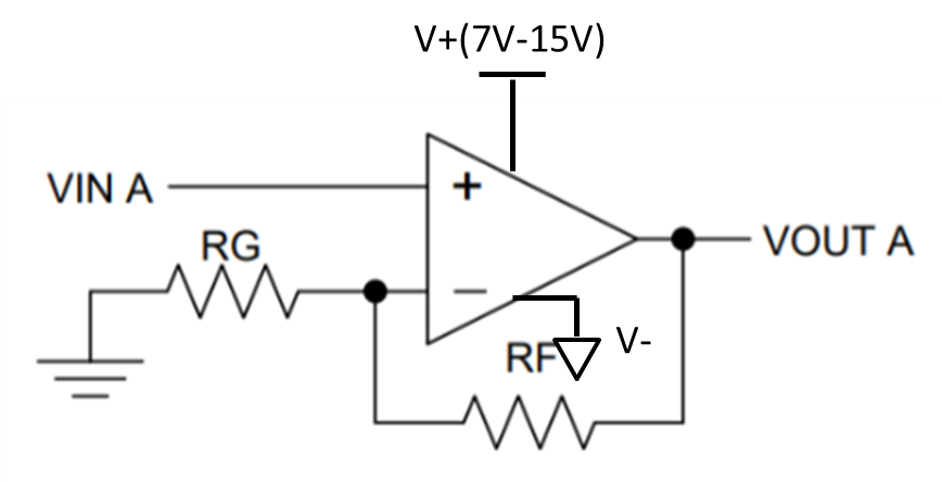
-Power supply : 7V - 15V

-Gain 55dB 

-Single end input and single supply

-Used only single channel

The output of OPA1678 would be input to TPA3131D2.

I could not see single-ended input and single-supply example in datasheet.

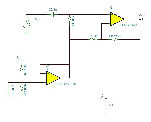
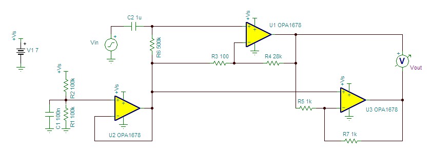
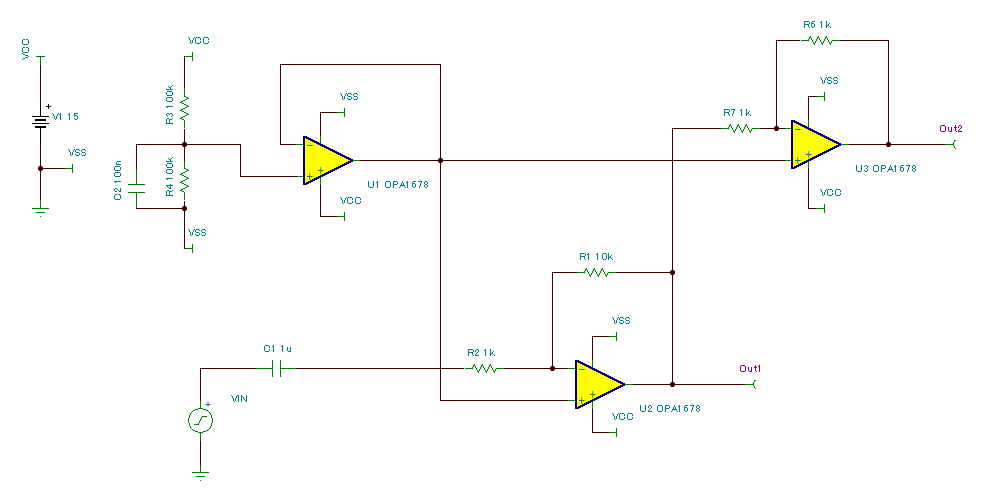
Can we use 1ch of OPA1678 like the following commonly op-amp use case?

BestRegards

  • Hi na na78,

    I'd suggest the following circuit:


    This will give you 55dB out to a 32kHz (52dB, or -3dB point). In order to use the OPA1678 as a noninverting buffer in this case, you'll need to bias the input to mid-supply. However, if only the noninverting input is biased, that bias will also be gained up through the amplifier. To avoid this, we make use of the second half of the OPA1678 to buffer R1, R2, and C1, providing a low-impedance mid-supply reference. This is then used to provide the bias for the noninverting input (through R3) and to bias the feedback network, ensuring that the output remains centered near mid supply. 

  • Hi Alex

    Thank you for your reply.
    It is helpful!

    By the way, TPA3131D2 used in follow stage can accept differential input.

    Could you tell us a circuit example to convert single-end input to differential keeping this gain?

    BestRegards
  • Hi na na78,

    I'd suggest the following:   

    There may still be some remaining DC offset in this circuit, so I'd recommend following the TPA3131D2's datasheet recommendation of AC coupling this circuit into the TPA3131D2 inputs. 

    In looking back at my previous post, I noticed an error in my schematic - U1A is drawn with feedback connected to its noninverting input and the voltage divider connected to the inverting input. These two connections should be reversed - feedback to the inverting input, divider to the noninverting input. 

  • Hi Alex

    Thank you for your reply.

    I used your recommendation circuit and modified a little.

    It is just change that the inverting input is used at U2.

    Do you see any problem on this circuit?

    BestRegards

  • Hi na na78,

    The only issue with this approach is that C1 and R2 form a high-pass filter at the circuit's input. 1kΩ with 1µF will set a -3dB point of 159 Hz, which is inside the audio range. If this is acceptable in your application, then this approach should work okay. Increasing C1 to 10-100µF would lower this -3dB frequency below the audio band. 

    One advantage of this approach is that your mid-supply bias only feeds high-impedance inputs (the noninverting inputs of U2 and U3), so buffering may not be required, allowing you to remove U1 and save an op amp channel in your design. 

  • Hi Alex

    Thank you for your reply.

    As you say, I should consider if C1 and R2 are in acceptable combination, thanks!

    And it seems to be advantage that one op-amp channel could be eliminated.

    I will talk with the customer in this consideration too.

    BestRegards