I am running the TLV320AIC3106 from the ADC to an MCU over I2S. The MCU then mirrors the data back on the I2S to the TLV320AIC3106's DAC. I am puzzled by the behavior because sometimes when I start it up it works really well but most times I start the chip there is significant distortion in the output.
I have narrowed it down to how the ADC is being configured. The DAC seems to be working and I have verified with a separate I2S amp that the distortion is part of the ADC's output I2S stream.
The code below is what I use to configure the part. The I2S is running at 32-bit 48KHz with a 48KHz*256 mclk into the part. I get similar results whether I am using the MCLK with CLKDIV or using the PLL. One difference is that when I run the PLL I have to clear the lower 3 bits of register 9 or I hear nothing at all. If I clear only bit 0 of register 9, I get static. That is just with the PLL on. With the PLL off, The bottom 3 bits of register 9 don't seem to have much effect.
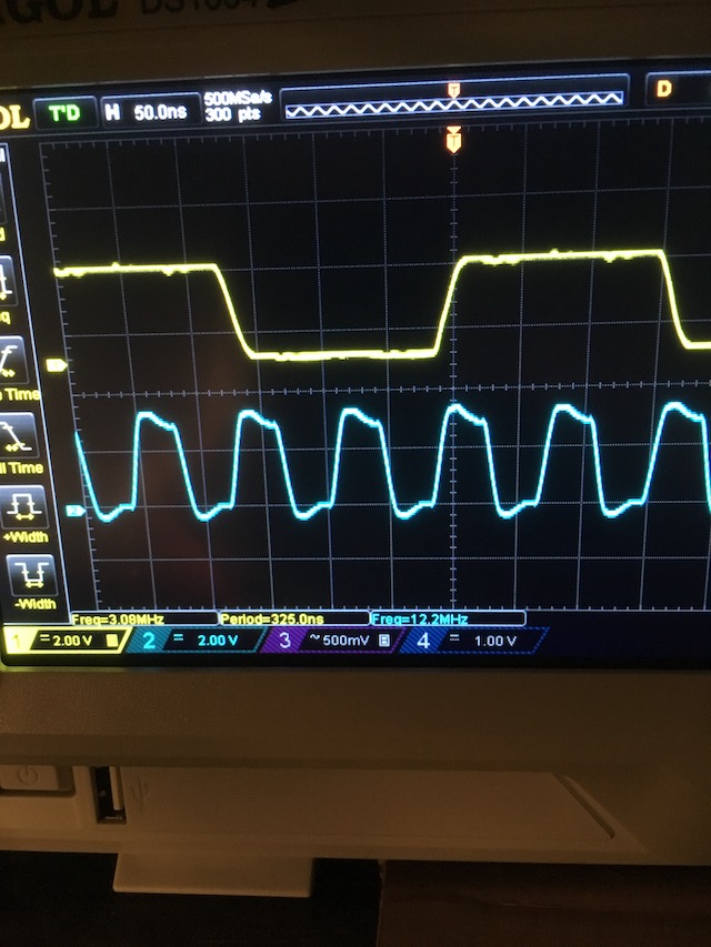
At this point, I have tweaked about everything I can think of. The issue seems to be with the clock so I included some scope shots below of the master and bit clocks as they go into the codec. I can't figure out if I am configuring something wrong or have a problem with signal integrity (or maybe power supply bring up?).
Thanks!
const tlv320aic_reg_t register_values[] = {
	{0, 0x00}, //select page 0 (there are only two pages)

	#if USE_PLL
	{102, 0x00}, //Clock control -- use BCLK
	{3, (1<<7)|(2<<3)|1}, //PLL Programming register A -- PLL ON Q = 2, P = 1
	{4, 8<<1}, //PLL Programming register B -- J = 32
	{5, 0x00}, //PLL Programming register C -- D = 0
	{6, 0x00}, //PLL Programming register D -- D = 0
	#else
	{3, (2<<3)}, //Q = 2
	{101, 0x01}, //Clock control -- use MCLK -- use CLKDIV_OUT for CODEC_CLKIN
	{102, 0x00}, //Clock control -- use MCLK
	#endif

	//{25, 1<<6},
	{7, (0<<5)|(1<<3)|(0<<1)}, //Codec datapath setup - dual rate?, Left DAC -> Left output, Right DAC -> Right output (this can be used to set the output to mono)
	{9, (3<<4)|(7<<0)}, //audio serial interface control register B, enable soft mute re-sync, 32-bit audio in I2S mode
	//{17, 0x0F}, //MIC3L/R input mixing LEFT -- left output from summing amplifier connected to left PGA mix - single ended
	//{18, 0xF0}, //MIC3L/R input mixing RIGHT -- right output from summing amplifier connected to right PGA mix - single ended
	//{20, 0x80}, //LINE2L to left input mixing  -- LINE2 is the CC input differential -- 0dB gain
	//{23, 0x80}, //LINE2R to right input mixing  -- LINE2 is the CC input differential -- 0dB gain
	{19, 0x84}, //LINE1L to left input mixing  -- LINE1 is the tablet input differential -- 0dB gain
	{22, 0x84}, //LINE1R to right input mixing  -- LINE1 is the tablet input differential -- 0dB gain

	//line out
	{37, 0xC0}, //Left DAC powered up, Right DAC powered up
	{41, 0x00}, //DAC Output control  -- Path L1 and R1 -- independent volume controls?
	{43, 0x00}, //Left DAC volume -- not muted
	{44, 0x00}, //Right DAC volume -- not muted
	{82, 0x80}, //DAC_L1 to LEFT_LOP/M
	{92, 0x80}, //DAC_R1 to RIGHT_LOP/M

	//power on outputs
	{15, 0x00}, //Left PGA not muted -- 0db Gain (can be set up to 59.5dB gain)
	{16, 0x00}, //Right PGA not muted -- 0db Gain (can be set up to 59.5dB gain)
	{86, 0x09}, //LEFT_LOP/M not muted and fully powered up
	{93, 0x09}, //RIGHT_LOP/M not muted and fully powered up

	{98, (2<<4)|(1<<3)}, //GPIO1 has clock output
	//{79, 0x09}, //?? MONO_LOP/M not muted and fully powered up

	//{94, 0xD8}, //Read only
	//{99, (2<<4)}, //GPIO2 control - jack/headset detect interrupt - we want lineout detect but not sure if this will work with that

	//Page 1 is all filter coefficients
};
Here is a shot of the bit and master clocks as they are going into the codec.