


Hello TI service team,
I build an amplifier with the TAS5731M in BTL mode. I am facing issus with the I2S clocks. The clocks are sourced by a DSP and have the following values:
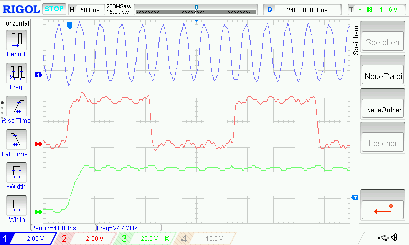
fs = LRCLK = 48 kHz; SCLK = 64 x fs = 3.072 MHz; MCLK = 8 x SCLK = 512 x fs = 24.576 MHz.
As far as I know, this clock configuration should work for the TAS5731M (datasheet). The clocks are all quite well shaped, stable and precise (see oscilloscope screenshot below, observe 50 MHz bandwidth for MCLK). Edges of SCLK and LRCLK fit together and I counted 64 SCLK periodes in 1 LRCLK periode. The clock source is also used with other devices and it works without any problems. That's why I suggest the problem is on the side of the amplifier.

The init routine I do on my system MCU is the following (/PDN is High):
1. Trim OSC: write 0x00 to 0x1b
2. Init system reg 2: write 0x00 to 0x05
3. set master volume: write 0x58 to 0x07 (-20 dB)
That works fine (small amount of noise is audible from the speakers after the init). But if I start to play audio, nothing happens.
While debugging process, I did the following:
1. reset error status register to see if the errors are persistent: write 0x00 to 0x02
2. read error status reg: it says sclk and lrclk error
3. read clock control register to see if the clock rate autodetection works: it says fs=48 kHz and MCLK=512 x fs, which is correct
4. read system control reg 2 to see if the amp is muted: amp is in normal operation (all channel exit shutdown), which is also fine. Moreover, I checked with the oscilloscope if the output stage is switching. It does like it should with about 384 kHz.
The question is, where could be the problem?
Thanks for any suggestions.
Greets, Markus.

