This thread has been locked.

If you have a related question, please click the "Ask a related question" button in the top right corner. The newly created question will be automatically linked to this question.

PCM3168A: Power-on sequence can cause SDA to stay low while in reset

Part Number: PCM3168A
Other Parts Discussed in Thread: OPA1654

We are using a PCM3168A CODEC in our design and we are having some issues.

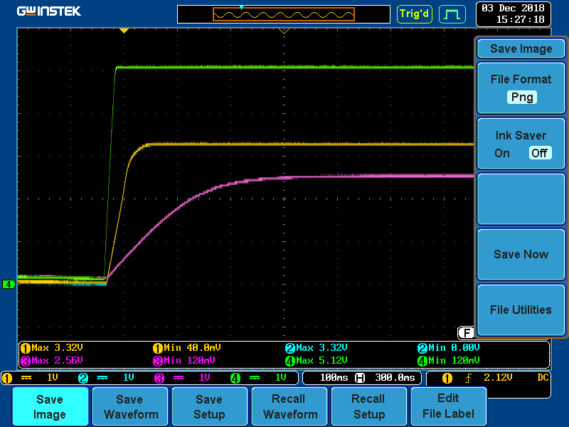
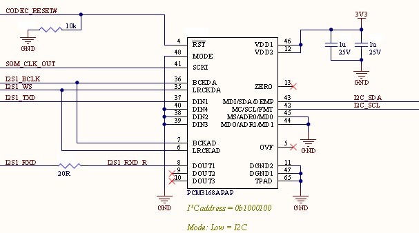
When powering-on (or power cycled), there is a chance that the CODEC will hold SDA low while in reset. We are using a pull-down to hold the CODEC in reset until the processor can boot and is ready to interface with the device. Once out of reset, the CODEC seems to sample the MODE pin correctly and, I will be testing a patch tomorrow to confirm, it works correctly despite the odd behavior during power-on. This normally wouldn't be an issue - however, the pin that is being used for I2C is required during the boot sequence of our iMX6 processor. If held low during power on, it prevents our processor from booting. This creates a deadlock that we cannot get out of.

We will be looking into pin swap the I2C signals during the next spin as this will avoid the deadlock. However, we are trying to understand what in the boot sequence can cause the I2C_SDA signal to remain low. We have numerous units already produced and we need to understand this to understand how it will affect the units we have in field.

From the datasheet:


Section 9.3.6 : The PCM3168A device does not require particular power-on sequences for VCC and VDD; it allows VDD on and then VCC on, or VCC on and then VDD on.

Section 12.1.1: Although the PCM3168A device has two power lines to maximize the potential of dynamic performance, using one common source (for instance, a 5-V power supply for VCC and a 3.3-V power supply for VDD generated from one common source) is recommended to avoid unexpected power-supply trouble such as latch-up or incorrect power-supply conditions. Also, simultaneous power-on/off of VCC and VDD is recommended to avoid unexpected transient responses in outputs, though the power-supply sequence of VCC and VDD is not specified in the operation and absolute maximum ratings point of view.


Our current power supply scheme powers both rail nearly-simultaneously. I also modified our power sequencing to delay the 3V3 rail until the 5V rail had powered-up, as would be the case if the 3V3 rail were to be generated with the 5V rail, to no avail.

Background information on the application:

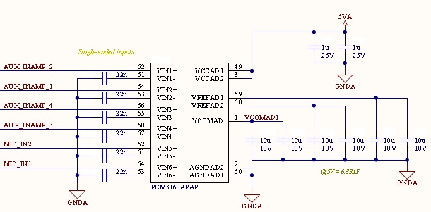
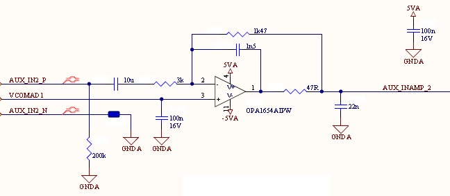
- All 6 AD inputs are used in single-ended with OPA1654, 22nF capacitors to AGND on VINn- signals.

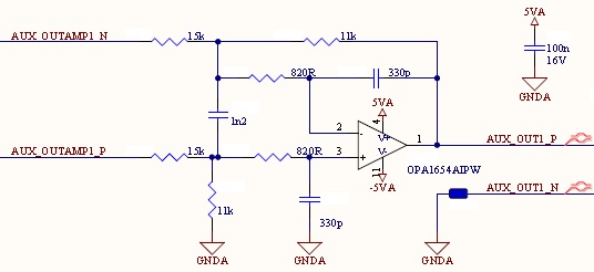
- All 8 DA outputs are used with OPA1654.


UPDATE 2018-12-05:

A patch using a bi-directional signal buffer with output enable (OE) connected to the CODECs reset (RST#) works. Once the iMX6 boots and asserts the RST# line high, the CODEC is fully operational. So this odd behavior is only present during the reset of the CODEC.

  • David,

    Our Applications engineer that supports this device is out of the office today, but will return tomorrow (12/5).

    best regards,
    -Steve Wilson
  • Hi, David,

    This behavior seen on SDA during Reset is odd for this part, but may be a consequence of the initialization process of this part, where maybe the I²C interface is not ready until the part is out of reset state. Do you have a pull-up resistor on the I²C lines connected directly to the PCM part?.

    Best Regards,

      -Diego Meléndez López
       Audio Applications Engineer

  • Good evening Diego,

    Indeed, I am wondering if this has to do more with the fact that there are multiple interfaces multiplexed on this line (as the part only samples the MODE pin upon assertion of the RST# pin) i.e. the IC configures this pin for another mode - or if it has to do more with some nuance in the power sequence. I am hoping you will be able to help me determine which case we are dealing with.

    We do have external pull-up resistors on both I2C signals.

    Best regards,

    David Bisson

  • Hi, David,

    Thanks for your feedback. Your assumptions are valid and in theory those are the possible issues which can be causing the problem. The main concern I have is that as this PCM3168A is a quite old part designed by a team which is no longer in TI, it is complicated to find information which could help us point out what could be the root cause. I can try some tests on the bench, but it may take some time as this part doesn't have an available evaluation module and is complicated to get one of the old boards. 

    Do you have a capture of the SDA line at the moment of power-up, reflecting the issue?.

     Best Regards,

      -Diego Meléndez López
       Audio Applications Engineer

  • Good morning Diego,

    Here is a scope capture of a boot into the fault condition, the pull-up on the line begins to pull the signal to the 3V3 rail before the CODEC boots and asserts the I2C_SDA signal low. The second capture is a reboot of the same setup that booted correctly.

    In both cases, CH1: 3V3 rail (measured at VDD); CH2: I2C_SDA; CH3: VCOMAD; CH4: 5V rail (measured at VCCAD).

    Not shown is the RST# signal which is low for the duration of the captures.

    Best regards,

  • Good afternoon Diego,

    It has been just over a week. Do you have any new information based on the screen captures of my last post? Have you managed to secure a old evaluation board to be able to do testing on your side?

    Please let me know where we stand and where we are headed on this issue.

    Best regards,
  • Hi, David,

    Sorry for the delayed response, I've been out of the office due Holiday season. I was able to test the device in a different board and I am unable to replicate the issue by keeping RST low, in this board the codec's I²C lines are working as expected. This makes me think that it is possible that something on your system is affecting the behavior of the PCM part. Is it possible to share a schematic of the PCM3168A on your system?.

    Best Regards,

      -Diego Meléndez López
       Audio Applications Engineer

  • Good morning Diego,

    Happy New Year.

    I have copied the sections of the schematic that pertain to the CODEC. For confidentiality reasons, all of the off pages and component designators have been removed - sorry for the inconvenience. Note the blue rounded rectangles (I left 1 designator - NT1), they are simply net ties.

    The CODEC is divided into the first 3 images:

    All 4 aux inputs are identical to the one shown in the image below. For the microphone inputs, it is the same circuit but the value of the components in the feedback loop are 2.2nF and 3kOhm instead of 1.5nF and 1.47kOhm.

    All 8 outputs are identical to the one shown in the image below:

    Best regards,

    David Bisson