This thread has been locked.

If you have a related question, please click the "Ask a related question" button in the top right corner. The newly created question will be automatically linked to this question.

OPA1692: Problem implementing OPA1692 LT Spice and on Breadboard

Part Number: OPA1692
Other Parts Discussed in Thread: LT1013, TINA-TI, OPA171, OPA1671, TPS7A4001

Ive been trying to run a simulation of the microphone preamplifier circuit that is in the data sheet for OPA1692.  I have imported the P-Spice model properly, but the solver never finishes crunching.  Ive found that if I do random things like add a 1ohm resistor to the VEE to ground it sometimes works.

Also, when I Put the evaluation sample chips that we purchased from TI on the breadboard in place of LT1013, the OPA1692's go haywire, where the LT1013s are stable.

I think this may be some power supply condition that differs, but the spice model seems to be broken or somehow incompatable with LTspice

  • Hi Alex,

    I would run a TINA-TI simulation with the OPA1692 TINA-TI reference design:

    www.ti.com/.../toolssoftware

    Kai
  • To update,

    Yesterday I redrew the entire circuit that I had in LT Spice into TINA-TI, then imported the OPA1692 Macro for the front end microphone preamp circuit.

    The simulation does work in TINA, so it is definately a problem importing that model to LT-SPice.

  • Hi Alex,

    as far as I know the models are optimized for TINA-TI.

    I have problems with LT-Spice from time to time, too, even with the models from LT. A good cure is to set realistic source impedances for the used voltage sources and current sources, as you already mentioned.

    Kai
  • Hi Alex,

    Our models should have no issues running in LTSpice or any other PSpice-based simulator. I've attached the mic preamp circuit from Figure 60 of the OPA1692 data sheet built up in LTSpice for your evaluation. You can run either an AC or transient analysis to verify the design performance.

    OPA1692 Preamp.zip

    Best regards,

    Ian Williams
    Applications Engineer/SPICE Model Developer
    Precision Amplifiers

  • Ian,

    THanks for your time on this.  I did confirm that the file above and model seems to work flawlessly in LTspice (so my computer is not too slow or anything), but the schematic I was refering to is the "Battery-Powered Preamplifier for Professional Microphones" in 8.3.2 of the OPA1692 Datasheet.

    In LT Spice when I run the OPA1692 model in a single supply circuit, (even basic unity gain buffer) it takes forever to crunch the simulation and more often than not hangs.  This is not the case with the identical schematic in single supply operation simulation in TINA-TI.

    Note: I am trying to power the IC from Phantom Power

  • Hi Alex,

    I have often seen that TINA-TI and LT-Spice get problems when the simulation runs into "illegal operating states", for instance when the input voltage exceeds the common mode input voltage range or the supply rails. Then the simulation progress often slows down and the processor begins to heat up. I guess this also happens when you simulate the phantom powered microphone circuit from section 8.3.2 of datasheet.

    Kai

  • kai klaas69 said:

     the phantom powered microphone circuit from section 8.3.2 of datasheet.

    THe circuit in 8.3.2 is not phantom powered, it is battery powered.

    Irregardless of phantom powered, battery powered, or operated from a supply, the spice model crashes in LT spice when operating in single supply mode, wheras it works fine in TINA-TI.

    I do suspect that there is some biasing condition that I am overlooking for the VS1/2 rail. However spice results are not corresponing

  • Hi Alex,

    the remote microphone circuitry is phantom powered. The OPA1692 is battery powered.

    I would remove the phantom power in the simulation. And I would also remove the diodes D1, D2, D3, D4 and the 10V zener.

    Kai

  • Hello Kai,
    Thanks for the input, however, like I said the "phantom power" is not an issue, I have removed that. When I mentioned phantom power in previous post I meant that ultimately I would be powering the OPA1692 with phantom power source i.e. XLR cable attached to resistors and regulated by Zdiode and or regulator.
    Interesting that you would suggest removing the ESD shottkey diode protection, however I have tried that as well.

    As I mentioned for some reason in LT spice, even when I run the models in a very simple unity gain buffer circuit the simulation tends to hang or be extremely slow.

  • Now I have been testin OPA1692 with the Evaluation Boards on the breadboard with inconsistant results. I am able to get a unity gain buffer to pass tone with a single supply, but ONLY on the Channel B (pins 5-8). Out of 9 sample units, most were stable with Channel B(pins 5-8) but all of them very unstable, and some broke down when trying the same unity gain buffer on Channel A (pins 1-3). I checked the pinouts 100 times and redid the breadboard 20 times. When I substitue an equivelent 2 channel opamp (LT1013) in the circuit it always runs fine on both channels.

  • Hi Alex,

    have you read section 8.1.1 of datasheet of OPA1692? Add an isolation resistor of 50...100R next to the output of OPA1692 and connect the scope probe behind this resistor. A scope probe can act as a considerable capacitive load. By the way, figure 63 of datasheet shows a 68R isolation resistor.

    It's no surprise that the LT1013 is much more stable, because it's a very very slow OPAmp. The bandwidth of OPA1692 is ten times higher and the slew rate is even 50 times higher! So, while the LT1013 forgives any breadboarding mistake, the OPA1692 behaves much more sensitive. That is completely normal.

    Kai

  • Kai,

    this makes sense.  I guess I didnt know what I was getting into with these ICs.  I feel like all the chips that I tried may have been overheated when I soldered the adapters, because they all have the same problem, stable on only on one channel.  Or maybe it is a biasing contition.

    What could I do to make these opamps more stable?

    Regarding the capacitive load and isolation resistor, that hasnt worked either and there is only negligable capacitive load at the output.

  • Hi Alex,

    normally it's very easy to get this OPAmp to work. Provide a good GND management by using wide and short GND copper traces, best in form of a solid GND plane. Use an isolation resistor at the output of 50...100R. Use a moderate gain and a small phase lead capacitance across the feedback resistance. Use a passive RC low pass filter, if the input signal carries EMV. That's it, like with any other OPAmp.

    It's absolutely unusual that only one of the internal amplifiers of a dual OPAmp is working and the other not. So, overheating during the soldering can definitely be the cause of your problems.

    Kai
  • Yes, I was able to get 3 units to work on breadboard.  Seems that I was overheating them when soldering the adapters, they are more fragile than I expected.  I gound another forum headfi with a guy who did the same thing with these opamps and had the same result (Lots of noise)

    Now that I have them working however I have run into another voodoo.  When I run the microphone preamp circuit by itself it works fine, but when I add another identical circuit

    to the breadboard and try to run them both, neither will work.  If I swap out one of the ICs for the LT1013 and use one OPA1692 they work together, but not two microphe preamp circuits with two OPA1692.  

    Back to my question about biasing.  the data sheet reveals no information about biasing other than the convoluted ESD schematic where it says that input current will run into the VS+ terminal etc...

    Are there any general recomendations for power supply and biasing that are specific to these opamps?

  • Hi Alex,

    can you show a schematic of your circuit?

    What do you exactly mean by "neither will work"?

    I would try to make the circuit run with a dual supply voltage first. This can make it easier to keep the input voltage within the recommended common mode input voltage range, as the OPA1692 is no input rail-to-rail OPAmp. Later you can rebuild the circuit for a single supply voltage.

    Again, keep an eye on your signal ground management! Use a solid ground plane or at least thick and short ground wires when breadboarding. Even when breadboarding the ground wiring can be heavily improved by routing additional ground wires to form a ground mesh.

    Kai
  • There are two of these Mic Pramp circuts on the breadboard.  Both share the same VS and VS/2.  They both work, when running on their own, but when both are plugged in something is being shunted and the VS drops to 5v (very low).

    If I change the opamp on one of the circuits to an LT1013 leaving the OPA1692 in the other they both work.  But if both circuits have the OPA1692, they dont work.

  • Hi Alex,

    it's dangerous to generate the bias with an OPAmp that is much slowlier than the OPA1692 itself. I would suggest to use the OPA171 for the biasing, as recommended in the datasheet. And have individual biasings for each microphone amplifier. I would also remove the 75R resistance at the output of biasing OPAmp, because it can introduce an unwanted feedback and cause instability.

    Kai
  • Thanks Kai,
    This is the thing i expected/wanted to hear. We have ordered the 171s but there was a problem with the website so we had to go to mouser. Anyway I had thought of this but was no way to test it. I appreciate the time youu have put into this tread, and will update the results when we receive the 171s.

    When you say dangerous, is it possible that this will damage the opamp?

    Happy New Year
  • Hi Alex,

    when the biasing OPAmp is too slow, its output impedance at higher frequencies can considerably rise. This can make the OPA1692 oscillate.

    Yes, damage can occur during oscillation, if the OPAmp heats up too much.

    Kai
  • I think that I have determined (somewhat by mistake) that it is in fact a power supply condition.  When I try to run more than 2 of these ICs off of phantom power the voltage regulator locks up and wont go past 4 volts.  It seems to have something to do with bypass capacitors and the startup time.  Meaning:

    When I run 2 1692s with an LT1013 it works as expected, but when I swap the LT1013 for a third OPA1692 the voltage regulator never fires up and stays at 5V (rather than 15V)

    seems something about the way the OPA1692 draws current is different.  I tried the above mentioned recomendations of higher slew rate opamp for biasing and seperate biasing opamps for each OPA1692 which didnt make a difference.  However (this is what I mean by mistake) when I swapped the OPA1692 with the LT1013 before the bypass caps on the voltage regulator were completely uncharged, I had 3 ICs running at the same time.

    I dont expect anyone to have a solution other than "your VR is ****ed up"

    I will update when I figure it out

  • Hi Alex,

    if you don't use the phantom powering, remove the 16V TVS. By the way, the TVS could draw too much current at 15V! Which TVS do you use?

    More, for the protection diodes I wouldn't take the Schottky rectifier 1N5817. Take better the 1N4148 or any other small signal diode. I like the BAV99, but is SMD.

    How do you provide the +15V supply voltage?

    Kai

  • I had thought of the diode protection as the problem, however i removed all of them and the problem still happens.

    I have been using a zener diode reference to a opamp error amp and pass transistor to provide the 15v

    Seems there is some startup problem when I use more than 2 of the OPA1692s.  Thats what I meant by "the way the 1692s draw current"  

    I will update with a schematic of power supply.

    Thanks for the recomendation of diode I will see if I can get those.  The TVS that im using is obsolete part SA16, the closest replacement is 1.5KE16A.  

    I chose the shottkey based on some other designs that I have found for input ESD protection.  What would be the advantage of the small signal diode for ESD on inputs?

  • Hi Alex,

    have you measured the supply currents of OPA1692? Insert a small resistor into the supply line and measure the voltage drop across it.

    Small signal diodes have the advantage of low leakage current and small parasitic junction capacitance. Leakage current introduces distortion and junction capacitance injects supply noise into the signal path. Usually, a small signal silicon diode is best for protecting against overvoltage. If very low forward voltage drop is necessary, which is not the case here, a small signal Schottky diode like the BAT54 or similar can be used. But the leakage current of a Schottky diode is much bigger compared to the leakage current of small signal silicon diode. And stay away from the 1A Schottky rectifier 1N5817! Its leakage current is huge, which makes it an absolute bad choice in this application.

    Kai

  • Some problem with voltage regulator.  It works fine with (2) opa1692 chips on VS but when I add a third OPA1692 it locks up and the 1000u cap never gets past 4.5 volts.

    However when I replace the third dual channel opamp for LT1013 it still works

    some MOSFET load switch somewhere can help?

    I will update when I have a better idea for Voltage Regulator.

  • Any Idea for load switch for Current inrush from OPAs maybe?
  • Any Idea for Load Switch? Maybe inrush current from OPA1692 causing regulator to lock up?
  • Hi Alex,

    Oops, have you removed the voltage regulator schematic? That's not good...

    Divide and conquer! First get the OPA1692 to work, then the voltage regulator circuit. Use a LM7815 voltage regulator to produce a stable +15V supply and fix the OPA1692 issues, if there exist any...

    Kai
  • The LM7815 requires 8mA Quiescent Current, so I can not even run it by itself from Phantom Power.
  • Hi Alex,

    anyway, first make the OPA1692 circuit to work! Otherwise you will never know, where the mistake is.

    Kai
  • Hey Kai,

    I did get all three OPA1692 ICs to work all at once with my regulator circuit (I made a couple of changes).

    But, It turns on only when there is no capacitor on the input of the Biasing (V/s2) opamp.

    In other words, If the the Vbias rail has a delay to charge the capacitor to VS/2, the OPA1692s will never turn on. This seems to only be the case when there are more than 1 OPA1692s on the same supply.

    THe problem now is how to filter the Vbias rail so there is no low frequency noise.

    There must be some spec or sequence for biasing that is not apparent from the datasheet. This goes back to my original question.
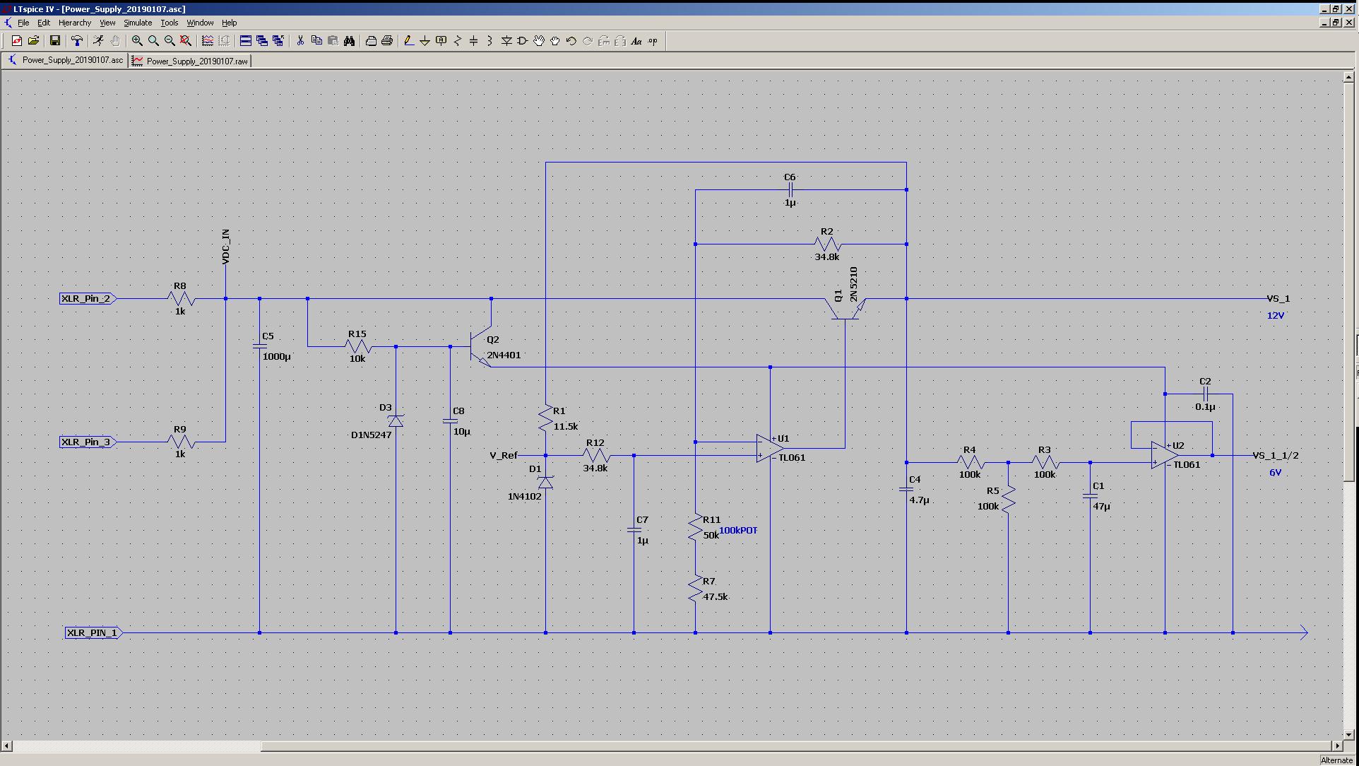
  • I have changed the original Voltage regulator circuit that I had posted.  The new circuit has a 18v preregulator that powers the Error amp.

    There is a Cap (C8) to ground at the base of Q2.  If the value of this cap is 10u, the OPA1692 ICs do NOT turn on, the regulator gets stuck at 3V (VS rail)

    If I increase the value of the C8 to 100u or more, everything works as it should.

    It has something to do with the VS/2 (Vbias) rail, because when I replace C1 with 1u, the opamps work regardless of C8.

    So I guess it is something about the difference between INput Voltage and Power Supply Voltage at startup.

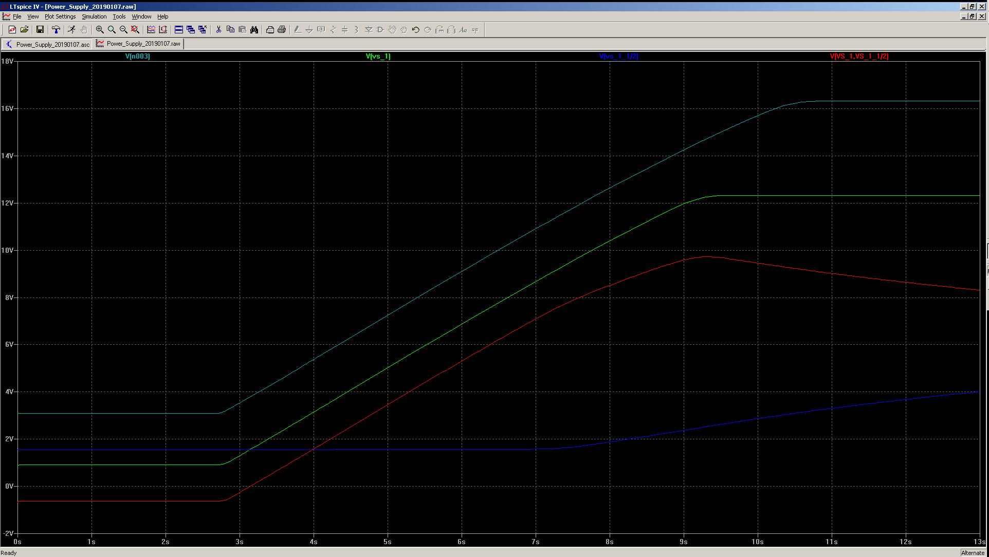
    Here are two graphs of the power supply startup with a Dummy load (no OPA1692 attached)

    The first one is with C8 at a value of 10u THIS DOESNT WORK

    The second one is C8 Value=1000u THIS WORKS

    Plotted are Pre-regulator Voltage (17), VS(12), VS/2(6) and the difference between VS and VS/2 during startup

    The answer is here, but I dont know what the spec is to determine a design without guess and check (because SPICE doesnt work with OPA1692 for this)

    Please advise

    Here is `10u for C8 startup, DOESNT WORK

    Here is C8 with 1000u WORKING! (also works with as low as 100u but hard to tell difference on graph):

    Here is the schematic for the Voltage regulator, It is powereing (3) OPA 1692 ICs from one Phantom Power XLR (48v)

    Values of C8 and C1 determine the cirucit working or not.  WHY?!

  • Hi Alex,

    you don't understand what I'm trying to tell you. Try to make the OPA1692 circuit work with a 15V regulator you can rely on, first, and not with a self fabricated regulator of questionable performance.

    Also, the microphone phantom power is not meant to power the microphone amplifier but only the microphone itself. More, only 3.5mA per line may be drawn from a 48V / 6k8 phantom power. So, your C5=1000µF is way too high and presents a short circuit during power-on.

    Kai

  • Kai,

    Do you have a recomendation for an adjustable voltage regulator IC that will input 48v and require very low Quiescent current (belown 1mA) and have low noise?

  • "More, only 3.5mA per line may be drawn from a 48V / 6k8 phantom power. So, your C5=1000µF is way too high and presents a short circuit during power-on."

    So what if it is a short circuit during power up? The 6.81k resistors from the Phantom power Source are there to limit the current, and thus are spec'd for this condition. Im not so worried about blowing out the phantom power resistors from the Mic Pre, thats why im using a cheap one with 8 channels to test. So far, no phantom power source has blown.

    As far as the phantom power current spec, It doesnt have to be 3.5mA per line, some Earthworks condeser mics draw up to 10mA on phantom power, I have checked this many times.

    Have you read the Phantom power for OPAMPs PDF supplied by TI (on the OPA1692 product information website)?
    www.tij.co.jp/.../sboa320a.pdf

    There is clearly a schematic with phantom power supplying current to two OPA1671 ICs. As a side note, the Quiescent current for the OPA1671 is actually higher than for the OPA1692 (per channel). So there is absolutely no reason for phantom power not to be used in this application.
  • Hi Kai and Ian - maybe a recap of the thread is in order because the issues I encountered have not been resolved.

    My buyer cannot place a bulk order for these components until the verification for our application is complete. Therefore, I will summarize the issues for clarity with the hope you can address them. Thank you for your patience.

    In a nutshell, the problem I’m having is turning on the opamps (OPA1692).

    First, we CANNOT use a standard voltage regulator, and frankly we don’t care to use, and can’t use, a standard voltage regulator like a LM7815 because it draws more current than our power source can provide, and we have found them to be an unacceptable source of noise.

    Our power source is an audio console which provides phantom power 48V (14mA short circuit current) through XLR connectors which we are stepping down to 12V, (approx 7mA).

    In our case, 6V is half voltage, which serves as our Vbias (see pic from TI datasheet below).

    As we began to find ways to turn on these OPA1692s, we found that there’s a particular startup condition that relates to the interaction between our half voltage supply (the voltage used to bias the chips, Vbias), and the supply voltage V+ (single supply).

    The way we got a circuit that includes three (3) OPA1692 chips to function was to build two voltage regulators, one which we are calling a “pre-regulator” and then the “regulator” to provide the 12V, 7mA we want for our application. In specific, we used a 17V zener diode along with a large value capacitor (>100uF) as the pre-regulator, and then an op-amp OPA171 based linear regulator to provide a 12V rail for Supply Voltage VS (V+).  The 12V is then divided as per OPA1692 datasheet using the OPA171 output as the Half Voltage (Vbias, 6V).

    Our issue is that if we use a larger capacitor (say 47u) in place of the 1uF shown in the datasheet schematic above, the OPA1692s microphone preamp circuits do not power on.  (Figure 63. Preamplifier for Professional Microphones Powered from a 9-V Battery)

    However, when the value of the capacitor in our pre-regulator 17V Zener is increased to >100uF then it works.

    The reason that we still require support for this is we would like to have some specification of OPA1692 which causes this to happen, and defines the power-on relationship between supply and bias voltage. (Yeah we found some kludgy way to make it work but we are not sure why it works.) If we don’t know why, then we can’t verify the part and my buyer will want me to use a different op-amp. I want to use OPA1692 for noise benefits.

    Also, none of this is apparent from SPICE simulations in TINA or LT.

    The OPA1692 spice model provided still does not work for single supply applications in LT-SPICE.

    Kai thank for your continued support here but we’d really like Ian to chime in.

  • Hi Alex,

    I think the OPAmp based voltage regulator does not work properly, because it sees a too high source impedance. I don't think that it has to do with the OPA1692 itself. That's why I asked you to test the circuit with a 15V standard regulator. With this test you would have found out, whether the issue comes from the OPA1692 or from the OPAmp based voltage regulator.

    For the supply voltage regulation I would take a low current zener diode like the TZMC12 and try a few circuit ideas.

    Kai

  • Hi Alex,
    A few thoughts:

    It's also possible that there's simply an issue with load, and that the changes in power supply ramp rate caused by the different capacitor values affect the quiescent current drawn by the op amps. A good way to confirm this would be to add a series resistance to the regulator output (and Vs/2 output, for good measure) and to measure the voltage across this resistor with an oscilloscope as you power up the circuit. It would also be worth observing the voltage at the collector of Q1.

    While your description makes it less likely, I wonder if there may be a bootstrapping issue with the regulator. Since you use your regulated output to generate your zener reference, you may want to provide a small amount of bias which would pull up the noninverting input of U1 to ensure the supply starts up correctly.

    Regarding alternative voltage regulators, it looks like TPS7A1601, TPS7A4001, and TPS79801-Q1 all support 50V or higher input voltages, low quiescent current, and reasonably low noise. Running a SPICE noise analysis of your Vs/2 circuit and amplifier circuit powered from a noise model of the TPS7A1601 did show an increase in voltage noise density at lower frequencies, but very similar RMS noise over the audio band.
  • Hello Alex

    Thanks for the Reply

    You are right and I have confirmed this that it is a load issue (not so simply).  

    After finding the charging (start up states) with the capacitors, I got a stable design, but then I couldnt get it to break again (even with removing the cap!)

    Tunrs out that It depended on my "dummy load" which I was using to "monitor" current draw for this low juice application

    When I put the "dummy load" back in, I was again able to "break" the OPA1692 circuits by adding a lage value cap on VS/2 (the VS/2 OPAMP input that is)

    Interesting you mentioned what you call "bootstrapping" for the regulator.  Yes in fact if you increase the value of C7 it does in fact lock up and VS outup will look very similar  to the other "lockup" situation.

    You can iimagine me tearing my hair out not knowing which cap was the culprit.

    Yes the way to find out which one is "locking" is to measure Q1 as you mentioned.

    I think I have found out how to make it work, and how to break it which is what I wanted.

    Once I got it up and running the performance with the OPA1692s is GREAT!

    now on to EQ problems