This thread has been locked.

If you have a related question, please click the "Ask a related question" button in the top right corner. The newly created question will be automatically linked to this question.

TAS5624A: Recommended Bulk and Decoupling Capacitors

Part Number: TAS5624A

Hi,

A shortage of MLCC supply is adversely affected the selection of the capacitor value, so could you please tell me the recommended minimum and maximum value for TAS5624A regarding the following decoupling capacitors ?
I understand that the decoupling capacitor with low ESR should be placed as close as possible to the pins of TAS5624A for high frequency decoupling with reference to the following application note.

- Input and Output Capacitor Selection
  http://www.ti.com/lit/an/slta055/slta055.pdf

- Power supply decoupling and audio signal filtering for the Class-D audio power amplifier
  http://www.ti.com/lit/an/slyt199/slyt199.pdf

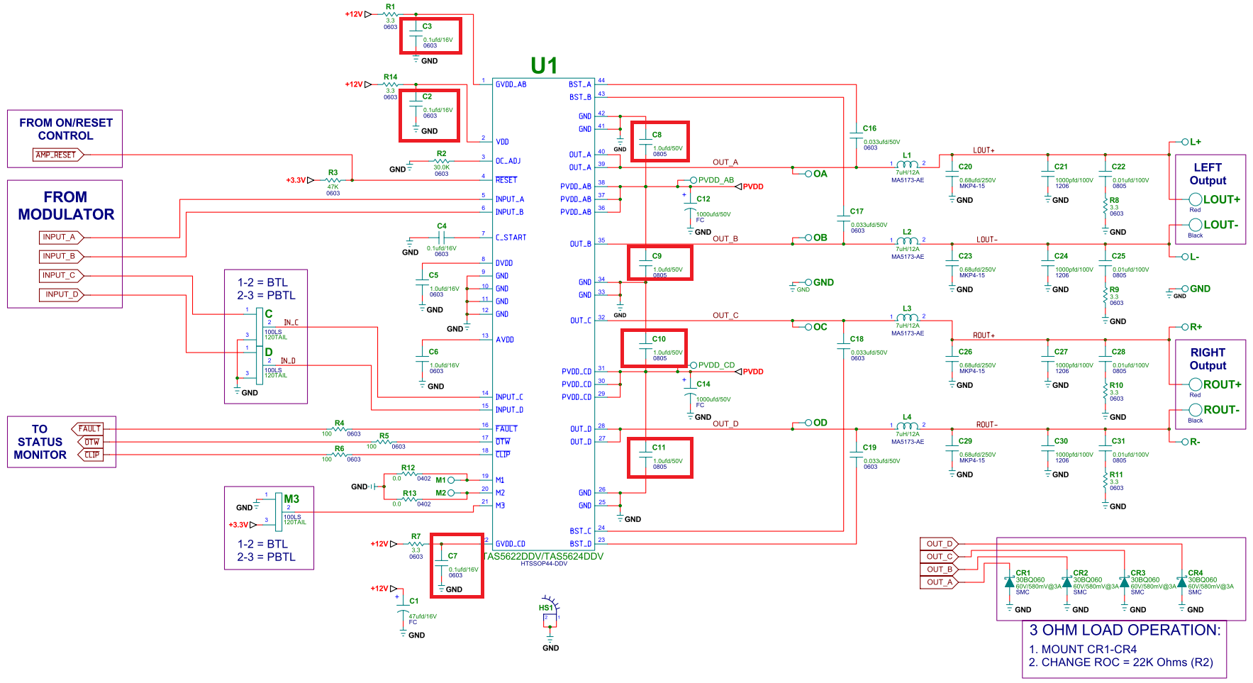
Q1. PVDD Decoupling Capacitors
It is recommended that two 0.22uF decoupling capacitors are placed, so could you please tell me the recommended minimum value if using one decoupling capacitor ?
MLCC with rated voltage range of 50V and X7R will be used.

Q2. Decoupling Capacitors for GVDD_AB and GVDD_CD
It is recommended that a 0.1uF decoupling capacitor is placed, so could you please tell me the recommended minimum and maximum value ?
MLCC with rated voltage range of 16V and X7R will be used.

Q3. Bulk and Decoupling Capacitor for VDD
It is recommended that 10uF bulk and 0.1uF decoupling capacitors are placed, so could you please tell me the recommended minimum and maximum value ?
MLCC with rated voltage range of 16V and X7R will be used.

Best regards,
Kato

  • Hi Satdanori-san,

    Let me see if I can answer your questions.

    1: The reason we have two decoupling capacitors is to decouple to all of the grounding pins.  If you have a chance, take a look at the TAS5624EVM schematic.

    2-3: The datasheet and EVM is the optimized values for these parts. 


    Hope this clarifies things.

    Best Regards,

    Robert Clifton

  • Hi Robert-san,

    Thank you for your prompt reply.

    I have already checked the following TAS5624EVM schematic, but I am confused because the recommended decoupling capacitors is different between the schematic which is mentioned in the data sheet and TAS5624EVM schematic as below.
    So, could you please tell me the limit value(maximum and minimum value) of each decoupling capacitor which can be used for TAS5624A if an optimum capacitor cannot be obtained ?

    Best regards,
    Kato

  • Hi Satdanori-san,

    My apologies, the decoupling capacitors used for PVDD are different on the EVM versus the datasheet.

    The decoupling capacitors used for the 12V rails are however the same values. They are just marked differently, as 100nF = 0.1uF.

    I would say that for the PVDD power supplies this means you have a min and max values of capacitance that we have tested and proven to have good performance. However I can only recommend the performance of 0.1uF decoupling capacitors for the 12V supplies.


    Best Regards,
    Robert Clifton
  • Hi Robert-san,

    Thank you for your quick response.

    I would like to confirm just in case, so is my understanding correct as below ?

    For PVDD power supplies it is recommended to use the decoupling capacitors from 0.22uF to 1uF.
    However, for 12V GVDD and VDD power supplies it is recommended to use only 0.1uF decoupling capacitor.

    Then I have an additional question, so is it possible to use two 0.047uF capacitors instead of a 0.1uF capacitor for 12V power supplies if an optimum capacitor cannot be obtained ?

    Best regards,
    Kato

  • Hi Satdanori-san,

    That is correct.

    I don't think using two 0.047uF capacitors instead of a 0.1uF would lead to any problems.

    Best Regards,
    Robert Clifton
  • Hi Robert-san,

    Thank you for confirming.

    I understood and will contact you if I have additional questions from our customer.

    Best regards,
    Kato