This thread has been locked.

If you have a related question, please click the "Ask a related question" button in the top right corner. The newly created question will be automatically linked to this question.

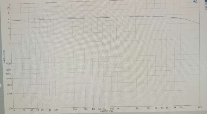
TAS5733L: During the test of TAS5733L/TAS5751M, we found that the high frequency signal part of TAS5733L/TAS5751M has a certain attenuation.

Expert 2630 points
Part Number: TAS5733L
Other Parts Discussed in Thread: TAS5751M,
During the test of TAS5733L/TAS5751M, we found that the high frequency signal part of TAS5733L/TAS5751M has a certain attenuation.
That is, after 10KHz, the output amplitude of the signal decreases gradually.           
Testing on TI's official development board TAS5751MEV, using PPC3 tool, testing Mono output, turning Equalizer off, using 4ohm false load:           
1.0dB 200Hz single-ended Vrms = 1.55V           
2.0dB 1KHz single-ended Vrms = 1.56V           
3.0dB 10KHz single-ended Vrms = 1.58V           
4.0dB 15KHz single-ended Vrms = 1.49V           
5.0dB 17KHz single-ended Vrms = 1.41V           
6.0dB 20KHz single-ended Vrms = 1.32V
As shown in the following figure:
That is to say, similar phenomena can be seen on TI's official development board.
What is the reason for this phenomenon? Is there a way to keep the high frequency output from decaying?
The schematic diagram of TAS5751M EVM development board:
TAS5751M EVM development board physical diagram:
  • what is your inductor selection? frequency repsonse is linked with L, C ,R selection. by the way, you can also use EQ to do compensation.
  • Hi Xiaolin,

    Thanks for your response.

    Do your mean the L5/L6 inductor value in the schematic?

    According to the document slou440, the L5/L6 is 15uH, and the C49/C50 is 0.68uF, so the fc of this LC filter is 49.8KHz.

    We use the TAS5751M Evaluation Module. We just connect one 4ohm resistor to J3, and test the power on the 4ohm resistor.

    And we find the power has a attenuation when the signal is high than 10KHz.

    Do you think the attenuation is expected?

    Thanks,

    Zhongbo Han

  • Hi Zhongbo,

    I think it is caused by the frequency response of the LC filter. You can see details by using tools attached:

    Class-D LC Filter Designer.xlsx

    Regards,

    Alix Wan.

  • Hi Alix,

    Thanks for your reply.

    We use the Class-D LC Filter Designer to simulate it. There is about -2dB attenuation at 20KHz for 4ohm load.

    So the attenuation is caused by LC filter.

    Thanks,

    Zhongbo.Han