This thread has been locked.

If you have a related question, please click the "Ask a related question" button in the top right corner. The newly created question will be automatically linked to this question.

TAS5720A-Q1: purpose of MCLK, and device shutdown questions

Part Number: TAS5720A-Q1


Team, 

My customer has some questions on TAS5720A-Q1, used in Software control mode:

1. What is the purpose of providing MCLK before bringing the device out of shutdown? Can I bring the device out of shutdown without providing MCLK and get the same performance?

2. When I bring the device out of shutdown, the device reports an OverCurrent Fault. This does not seem to affect device functionality. There doesn't seem to be an OverCurrent Fault.

3. Our software people are reporting that the device is handling 16-bit data weirdly and have resorted to using 15bit data. Is this a known issue/situation with the device?

Thanks

Viktorija

  • Hi Viktorija,

    1. The MCLK is used for system clock tree. so MCLk is always required for device function normally.

    2. How is the behavior after OC reported? Did device shutdown and fault pin latched. If yes, what is the inductor saturation current? you ask customer to use current probe measure the current going through inductor? And please also get the schematic.

    3. May you give more details about this weird situation?  is it 16bit IIS? How is the 15bit sequence?

    Dylan

  • Per customer:

    We've been able to get the amplifier mostly working on our in-house board.

    We had some hardware issues earlier which were preventing us from correctly configuring the amp, which have now been fixed.

    1) Added some pull-up resistors on the I2C addr and sleep lines to prevent I2C errors.

    2) Changed I2C pull-up to bring the rise time within spec.

    We can now reliably configure the amp, and are using the following startup sequence, based on section 9.2.1.2 of the datasheet.

    // Disable amp                                                              

       gpio_write(spkr->shutdown_pin, false);   // Shutdown enable                

       // Put the amp in shutdown mode                                            

       write_cmd(0x08, 0xFC);                                                      

       // Mute the amp (via the I2C interface only, DO NOT use the mute gpio pin)  

       write_cmd(0x03, 0x83);                                                      

       // Set the reserved bit 7 of the analog control register                    

       write_cmd(0x06, 0xD1);                                                      

       // Bring the amp volume : 0x07 (-100 dB) to 0xFF (24 dB) with 0.5 dB increments

       // volume (dB) = 0.5 * val - 103.5                                          

       write_cmd(0x05, 0xCF);                                                      

       // Bring the amp out of shutdown mode                                      

       write_cmd(0x08, 0xFD);                                                      

       // Enable amp                                                              

       gpio_write(spkr->shutdown_pin, true);     // Shutdown disable              

       // Put the amp in shutdown mode                                            

       write_cmd(0x08, 0xFC);                                                      

       // Unmute the amp (via the I2C interface only, DO NOT use the mute gpio pin)

       write_cmd(0x03, 0x81);                                                      

       // Bring the amp out of shutdown mode                                      

       write_cmd(0x08, 0xFD);                                                      

    }                                                

    However, there is one more issue which I haven't been able to figure out.

    I2S 16-bit signed data not working

    It looks like the amp is unable to correctly process 16-bit I2S signed data. I can see via a logic analyzer that I'm sending the data correctly, and the logic analyzer can interpret the data as standard I2S 16-bit signed data.

    However, I need to make the following changes to the data to get the expected output from the amp.

    1) Convert the signed data to unsigned data

    2) Divide by 2, i.e, effectively use only the bottom 15-bits

    I've tried using sawtooth/sine waves and observed that the data gets clipped if we're using the 16th bit (MSB)

    This workaround indicates to me that the amp is expecting

    - unsigned data

    - operating only on the bottom 15 bits of the data

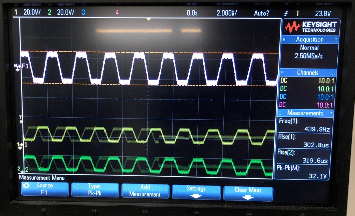
    I've attached three scope plots from a 440 Hz sine wave. The purple signal is the differential voltage at the amp outputs.

    As you can see, only the unsigned, 15-bit plot looks correct.

    Not sure what I'm missing here. Do we need to do something additional in the register configuration?

    Any help will be most appreciated.

  • Dylan,

    Update from my customer:

    Further investigation revealed that when I send 1's complement data, I'm seeing the correct signal, without any DC bias. (see scope plot), and full 16-bit scale output

    This is what I originally expected to see with 2's complement data, i.e, the I2S spec.

    Is it possible that this amp accepts 1's complement data, and not 2's complement data, as specified in the datasheet?

    Thanks

    Viktorija

  • Update from customer - so 2's complement is working as advertised!
    The issue was that the signal was getting clipped at the default gain setting, and by reducing the digital gain I'm able to now get a clean signal.
    Sorry for the confusion :)