This thread has been locked.

If you have a related question, please click the "Ask a related question" button in the top right corner. The newly created question will be automatically linked to this question.

TAS5720A-Q1: Strange Over Current Error

Part Number: TAS5720A-Q1

Hi,

I am designing device that uses TAS5720A amplifier, which is connected to STM32F4 microcontroller. When I'm sending audio to the device it immediately stops outputting signal and sets OCE flag (0x08 register reads 0x04). This does not occur when I'm sending zeros or values really close to zero. It doesn't matter if I connect 10 ohm resistor as a load, or leave output connectors open. I've tried various I2S and sampling rate settings. I've also tried to slow down PWM frequency, but this also didn't made any change. I've checked I2S signals using oscilloscope and they seems fine. I've even replaced TAS5720 with new one which also didn't made any difference. I am guessing that problem doesn't lie in communication  between microcontroller and amplifier, but where? Do you have any idea what am I missing?

Schematic:

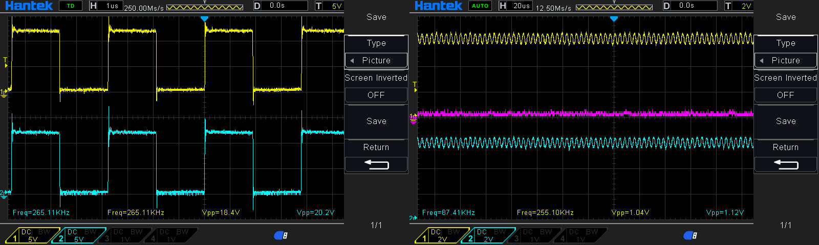
LRCK and SDIN signals while sending 32-bit "17000" value using Right Justified 24-bit audio format, device works (reg 0x08 == 0x00):

LRCK and SDIN signals while sending 32-bit "32768" value using Right Justified 24-bit audio format, device throws OCE (reg 0x08 == 0x04):

  • Hi Pitor,

    May you check register 0x02 and 0x06, so we can know the status of the device.

    And can you clarify what is the output amplitude under the test of "It doesn't matter if I connect 10 ohm resistor as a load, or leave output connectors open."

    BTW, do you have a current probe to measure the current flowing through iductor?


    Dylan
  • Hi Dylan,

    These are all registers dumped from the amplifier after configuration but before sending any data different than zeros:

    [TAS5720A][0x00] = 0x00
    [TAS5720A][0x01] = 0xFD
    [TAS5720A][0x02] = 0x80
    [TAS5720A][0x03] = 0x80
    [TAS5720A][0x04] = 0xCF
    [TAS5720A][0x05] = 0xCF
    [TAS5720A][0x06] = 0x01
    [TAS5720A][0x07] = 0x00
    [TAS5720A][0x08] = 0x00
    [TAS5720A][0x09] = 0x00
    [TAS5720A][0x0A] = 0x00
    [TAS5720A][0x0B] = 0x00
    [TAS5720A][0x0C] = 0x00
    [TAS5720A][0x0D] = 0x00
    [TAS5720A][0x0E] = 0x00
    [TAS5720A][0x0F] = 0x00
    [TAS5720A][0x10] = 0xFF
    [TAS5720A][0x11] = 0xFC

    This is output of amplifier without load resistor. All signals are measured in reference to circuit's ground. On the left there are SPK_OUT+ and SPK_OUT-, on the right signal after filter. Pink signal is the difference between outputs:

    The same signals after connecting 4.7 ohm resistor to filter output:

    This is signal on SPK_OUT+ and SPK_OUT- after removing filter, without load:

    When OCE occurs, there is about 150-200mV of constant voltage on both outputs. Value that I have to send to get the OCE seems to be the same, no matter if there is load or not, or if there is filter. I've also tried to remove bootstrap capacitors. If they are removed, I get OCE no matter what I send. I've soldered them with 27 ohm resistors in series to measure if there is any significant current, but voltage drop on resistors was almost unnoticeable.

    Unfortunately, I don't have current probe.

    Piotr

  • I guess I resolved my issue. During configuration I was setting Analog Control register (0x06) to 0x01, clearing 'Reserved' bit. After setting it to its original value (which is 1; now reg 0x06 is set to 0x81), amplifier started working.
  • Congratulations!